EMC Testing Part 1 - Radiated Emissions
By Eur Ing Keith Armstrong C.Eng MIEE MIEEE, Partner, Cherry Clough Consultants, Associate of EMC-UK
Tim Williams C.Eng MIEE, Director, Elmac Services, Associate of EMC-UK
This is the first in a series of six bi-monthly articles on 'do-it-yourself' electromagnetic compatibility (EMC) testing techniques. This series will cover the whole range of test methods - from simple tests for development and fault-finding purposes, through lowest-cost EMC checks; 'pre-compliance' testing with various degrees of accuracy, on-site testing for large systems and installations; to full-specification compliance testing capable of meeting the requirements of national test accreditation bodies.
Of course, what is low-cost to an organisation of 5000 people could be thought fairly expensive by a company of 50, and might be too expensive for a one-person outfit, but we will cover the complete range of possible costs here so that no-one is left out. Remember though, that the more you want to save money on EMC testing, or reduce the likelihood of being found selling non-compliant products, the cleverer and more skilled you need to be. Low cost, low risk, and low EMC skills do not go together.
This series does not cover management and legal issues (e.g. how much testing should one do to ensure compliance with the EMC Directive). Neither does it describe how to actually perform EMC tests in sufficient detail. Much more information is available from the test standards themselves and from the references provided at the end of these articles.
The topics which will be covered in these six articles are:
1)Radiated emissions
2)Conducted emissions
3)Fast transient burst, surge, electrostatic discharge
4)Radiated immunity
5)Conducted immunity
6)Low frequency magnetic fields emissions and immunity; plus mains dips, dropouts, interruptions, sags, brownouts and swells
7) Emissions of mains harmonic currents, voltage fluctuations, flicker and inrush currents; and miscellaneous other tests
Table of contents for this article
0 EMC testing requirements throughout the life-cycle....................................................................... 2
0.1 Development testing and diagnostics........................................................................................ 2
0.2 Compliance and pre-compliance testing.................................................................................... 2
0.3 QA testing............................................................................................................................. 2
0.4 Changes and variants.............................................................................................................. 3
0.5 Getting the best value from a third-party test lab........................................................................ 3
1 Radiated emissions........................................................................................................................ 3
1.1 Close-field probes................................................................................................................... 3
1.2 Current probes....................................................................................................................... 4
1.3 ‘Bug detectors’....................................................................................................................... 5
1.4 Antennas............................................................................................................................... 6
1.5 Using oscilloscopes for development, diagnostic, and QA testing................................................ 7
1.6 Using spectrum analysers for development, diagnostic, and QA testing....................................... 7
1.7 Using radio receivers for development, diagnostic, and QA testing............................................... 9
1.8 ‘Pre-compliance’ testing.......................................................................................................... 9
1.9 Repeatability, and ‘golden product’ testing.............................................................................. 11
1.10 Open versus closed test sites................................................................................................ 13
1.11 On-site testing of systems and installations............................................................................ 15
1.12 Full compliance testing......................................................................................................... 16
1.12.1 The test site............................................................................................................. 16
1.12.2 Testing procedures.................................................................................................... 17
0 EMC testing requirements throughout the life-cycle
Before we begin looking at radiated emissions testing, we should consider that there are many different needs for EMC testing during a product's lifecycle, each with its own technical, cost, and time requirements.
0.1 Development testing and diagnostics
It can help save a great deal of time and money if EMC testing is done at all stages in a product's development.
When the product has finally come together in its intended enclosure, it can be tested using standard EMC test methods. But standard methods are not very useful in the very early stages of a project when, for example, microprocessor or DSP chips are being chosen (some of which emit 40dB more than other similar types).
Neither are standard 'EMC test lab' test methods of much use in a late stage of a project when remedial work is required to solve a radiated emissions problem, because they can't easily tell you where the emissions are coming from.
So we need to use different techniques for development and diagnostic testing, and these often employ close-field probes, current probes, and bug detectors.
0.2 Compliance and pre-compliance testing
Full testing to standards is required for imports into many countries world-wide, often in specified test laboratories. The EMC Directive only requires manufacturers to make a Declaration of Conformity listing the test standards they have "applied" when using the standards route to conformity. Quite what is meant by "applied" is not terribly clear, but what is clear is that customs officers in the EU have no legal right to insist on seeing any EMC test report or certificate as a requirement for any goods supplied in the EU. EU EMC directive enforcement officers may ask to see evidence that 'due diligence' has been achieved in the conformity of a given product at any time (most usually after a complaint by a competitor).
While full compliance EMC testing is not a burden for manufacturers of products made in large volumes, it can be disproportionately expensive for manufacturers of low-cost custom engineered or small-batch products.
So there is a need for pre-compliance testing to discover whether there are any 'show stoppers' before a mass-produced item goes for full compliance testing. Such pre-compliance testing has the advantage that tests can be stopped at any time, the equipment under test (EUT) modified and the test restarted; whereas full compliance testing is more expensive per day and allows no disruption in the test, or involvement by the EUT's designers.
If pre-compliance testing is good enough to pass the 'due diligence' requirement of the enforcers, it can be all that is needed for legal sales in the EU - good news for manufacturers of low-cost custom or small-batch equipment.
0.3 QA testing
The fact that one example of a product in serial manufacture passed an EMC test once upon a time proves absolutely nothing about whether the units being made or sold today would pass that EMC test - unless the manufacturer has adequate EMC procedures methods embedded in his QA programme.
Such a QA programme will generally involve at least the following:
- Design to reduce the large variabilities that can occur in EMC performance in serial manufacture due to different components, assembly, or wiring practices to manageable proportions.
- Control of all changes, production concessions, variants, software bug-fixes and upgrades, to ensure that they don't compromise EMC performance.
- Sample-based EMC testing in serial manufacture.
The types of EMC testing that are useful in development and diagnostic work can often be integrated into a production line to improve confidence in EMC compliance. Access to reasonably good pre-compliance facilities (at least) is also required for sample-based EMC testing will also be required by volume manufacturers.
0.4 Changes and variants
It is rare for a product to be manufactured in volume for years without incremental changes, perhaps to improve manufacturability; overcome a problem with component supply; fix bugs in the software; add new features or improve existing ones; or produce variants to suit new markets. EMC testing in these situations usually involves the types of test methods used during development, pre-compliance test methods, and/or QA. An understanding of how the change is likely to affect EMC can help by restricting the tests to those most likely to show a degraded performance.
0.5 Getting the best value from a third-party test lab
Test laboratories can be very helpful, and provide very good value for money if used intelligently. Many of them can be hired by the hour, or half-day, for pre-compliance or 'look see' testing. If you ask them, they will make sure that a skilled tester or EMC remedial work expert is on hand to help you achieve what you want.
It is best to create a test plan (usually with the help of the lab concerned) well before going to do any testing, so that you have all the leads, connectors, software, and auxiliary equipment necessary so that expensive laboratory time is not wasted.
During pre-compliance testing it is especially useful to send along development engineers with the necessary equipment and components to do remedial work in a hurry, spending an hour or two with a soldering iron instead of having to re-book for a re-test in a few more weeks time. 'Murphy's Law' applies to EMC testing too - if you haven't prepared for something, it will turn out to be embarrassing and costly.
Reading and understanding the test standards yourself, and then watching how the test labs do their work, is a good way of learning how to do your own tests.
1 Radiated emissions
This section focuses on testing to radiated emissions to the typical domestic/commercial/industrial EN standards over the frequency range of 30MHz to 1GHz. Some people will need to measure above 1GHz, for example for some types of radio-frequency (RF) equipment when applying EN 55011 (CISPR11), or when meeting FCC requirements for the USA with a product containing a clock of over 108MHz. Some people need to measure below 30MHz, for example when measuring cable TV distribution systems. Military radiated emissions testing also covers a much wider range than 30MHz to 1GHz. Let's start by taking a look at the radiated emission transducers commonly available.
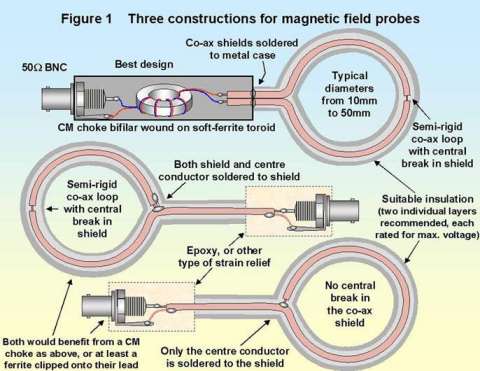
1.1 Close-field probes
Close-field (also called 'near-field') magnetic and electric field probes are low-cost to buy and very quick and easy to make. They are commonly used in development, diagnostic and QA work. There are many articles and papers describing how to make various versions of such probes, and most EMC test equipment manufacturers also sell their own versions of them. Figure 1 shows the three main constructions for magnetic field probes.
Near-field probes should always use 50W cables, and the input impedance of the RF measuring instrument they are connected to should also be 50W. Where the test instrument does not have a 50W input option, use its high-impedance input but fit a 50W BNC terminator at the instrument end of the probe's cable, for example using a BNC 'Tee' piece or through-line terminator. The 50W termination helps stop resonances in the probe cable which would otherwise occur when its length exceeds one-tenth of the wavelength of the highest frequency of interest (e.g. 50W termination is necessary for cables longer than 300mm for a highest frequency of only 50MHz - remembering that the wavelength for a signal in a cable is roughly half that of an electromagnetic wave in free space).
Figure 2 shows a standard electric field probe design, and also a 'pin probe'. The pin probe is a voltage probe which makes contact to the circuit or metalwork of interest via a 10pF capacitor, and it picks up the common-mode (CM) voltage as well as the signal voltage. CM voltage is a big contributor to radiated emissions. Magnetic field probes are shielded so that they don't pick up electric fields, which can sometimes leave them 'blind' to an important source of emissions. Usually, for small products, it is the CM currents leaking out via cables that cause most of the radiated emissions, but sometimes it is the electric field caused by the CM voltage on the body of the EUT itself, so electric field or pin probes have an important part to play.

An example of a proprietary probe set is shown in Figure 3. Since radiated emissions are caused by both electric and magnetic fields, it can help to use unshielded loop probes such as those shown in Figure 4. These are sensitive to both types of field, so their output is not as calculable or predictable, but they can save time when all that is needed is a check to see where an emission is coming from.
The probes shown in Figure 4 are not well insulated, so care must be taken when using them not to short something out and damage the EUT, or damage the test instrument they are connected to, or cause electrocution or fire. Encasing a probe in thick plastic or resin is always a good idea, and may be necessary to meet health and safety regulations.

FIGURE 4

All loop probes are directional, so when hunting for sources of emissions they should be used in two or even three orientations to make sure that the strongest signals have been picked up.
The loop probes shown above are good for frequencies up to 1GHz, with the smaller diameter loops (e.g. 10mm) having a better high-frequency response but less sensitivity at low frequencies. Probes with more than one turn are more sensitive at lower frequencies, but their inter-turn capacitance reduces their high frequency response considerably. Most designers will want to have a variety of probe sizes handy, so they can check they are not missing any important emissions at low or high frequencies. Readers interested in frequencies above 1GHz will find the 'toothpick' and other probes described in [1] interesting. A great deal of useful diagnostic information can be obtained by intelligent use of close-field probes, as described in [2] and its references.
1.2 Current probes
[3] is a most useful document for anyone interested in doing low-cost testing themselves. In one of its papers: "Radiated emissions pre-compliance diagnostics" Tim Williams describes a current probe based on a ferrite core and easily made by any electrical engineer. It is really just the close-field magnetic loop probe described above, coupled closely to the cable being measured by passing them both through the same hole in the middle of a ferrite cylinder.
These current probes only measure the CM field from the cable, whereas close-field loop probes measure differential-mode and CM at the same time, depending on where they are placed in relation to the conductors in the cable. Since it is usually the CM currents which create most of the radiated emissions problems from cables, measurements using such current probes can have a better correlation with the results from proper EMC tests.
Current probes can easily be calibrated if a signal generator that covers the frequency range of interest is available (if it isn't, your local EMC lab may let you use theirs for a small fee, or you could hire one).
Using the split-ferrite cylinders usually sold as clip-on EMI suppressers for the core, a calibrated current probe can be clipped over a cable of interest and its CM currents measured for both their frequency and amplitude. The probe produces a voltage output which is related to the CM current in the cable, and should be terminated in 50W at the measuring equipment.
Figure 5 shows a practical example of such a probe, constructed from ordinary co-axial cable. It uses a Kitagawa FGC3M3 screen-bonding clamp to avoid damaging the dielectric of the co-ax by soldering its braid. The ferrite core used was a standard 32mm long split-cylinder of the type readily available from a number of ferrite suppresser manufacturers and electronics distributors. The length or shape of the split ferrite core is not critical, but it should have a clamping arrangement that allows easy assembly and dis-assembly, and it needs to have an internal diameter large enough to pass both the cable to be tested and the probe's own cable through at the same time. Note the calibration of such a probe will be specific for a particular ferrite part.

Ott and Paul's simple formula E = {1.26 x 10⁷ x F x L x I} can be used to assess whether the cable currents measured by this ferrite-cored probe are likely to cause unacceptable radiated emissions. In the formula: E is the radiated emission in Volts/metre at 10 metres distance and can be converted to dBmV and directly compared with the limits of EMC emissions standards; F is the measured frequency in MHz; L is cable length in metres; and I in mA is the current measured by the probe at the frequency F (having taken the probe's calibration factor into account).
Another very useful paper from [3] is "EMC diagnostic techniques" by Tony Maddocks of ERA Technology. This includes a graph which is a useful alternative to Ott and Paul's equation above, allowing emissions to be estimated as a function of the height of the cable above a ground plane.
Tony also describes the use of calibrated current probes, which are simply proprietary versions of Tim's split-ferrite probe and can be hired or purchased at reasonable cost from a number of suppliers. These current probes are supplied already calibrated, with a graph of their mV/mA conversion factor versus frequency to prove it. Notice that mV/mA is just an impedance in W, often called the transfer impedance when applied to probes like these.
Tektronix have almost always had current probes in their range of accessories, usually only capable of measuring up to 50MHz. But now they also offer a much smaller current probe that measures up to 2GHz.
1.3 'Bug detectors'
These go under a variety of names, but most of them just indicate the total field strength and give no frequency information. They usually consist of some form of antenna (e.g. a tiny dipole, used well below its first resonance so it has a broadband response) followed by a wideband detector and an amplifier driving a meter or a column of LEDs. There are a number of articles published in trade and hobby magazines on how to build these, and a number of commercial products also exist.
Many of these detectors are intended to be used for determining whether the fields present are a hazard to human health, and may not be sensitive enough to measure electric fields below 1Volt/metre (V/m). 1V/m is the same field strength as 120dBmV/m (dBmV/m being the quantity usually used when measuring radiated electromagnetic fields above 30MHz) and so they are useless when it comes to seeing whether your product emits more than 37dBmV/m (say) at the normal measuring distance of 10 metres. They are often more useful for taking onto a customer's site to quickly determine whether there are strong fields present that may be causing a product to malfunction.
However, if the bug detector is sensitive enough it can be used close to a product to detect strong sources of emissions which might cause a problem on a proper radiated field measurement, and there are one or two models which are sold for this purpose. Given sufficient sensitivity they can be handy for development, diagnostic and QA work in much the same way as the close-field probes and current probes described earlier. Examples of some commercially-available 'bug-detectors' are shown in Figure 6.

Because bug detectors generally don't provide frequency information they aren't a great deal of use in any detailed assessment of radiated emissions, but they have some big advantages in that they are self contained, easy and quick to use, portable and battery powered. They are good for relatively unskilled use and in the field.
It is sometimes possible, with some experience of the detector and the type of product, to scan the surface of a product and along its cables with one of these probes and predict whether the product would pass a proper radiated emissions test. To have any real confidence in the ability to use a bug detector in this way requires considerable experience with using the detector on a variety of products that are known to pass and to fail their radiated emissions tests.
However, these bug detectors can be used in a QA mode: to quickly scan at least the known weak points for emissions of a product in serial manufacture; or to check that the products which are being shipped are likely to have a similar radiated emissions performance to the ones that have been more accurately tested. Checking areas such as cable terminations and connectors can reveal incorrect assembly (such as the use of a pigtail instead of a 360o clamp for a cable screen, or anodised aluminium used instead of alochromed). But deciding what the pass or fail limits on the detector's display should be, for the various parts of a product and its cables and connectors, requires experience with how the detector responds to the kinds of problems which could lead to a failure on a proper test.
1.4 Antennas
Full-compliance tests for radiated emissions use antennas designed for use in the far field, and EMC standards only give emissions limits in the far field. The far field is generally defined as greater than one-sixth of a wavelength, which for 30MHz is 1.7 metres.
When measuring radiated emissions below 30MHz, getting far enough away to measure in the far field is impractical. So below 30MHz it is usual to measure the magnetic field and electric field components separately, in the near field, using large loop probes (typically 600mm diameter) and whip antennas (typically about 1 metre long).
Between 30MHz and 1GHz dipoles can be used, but they have a limited frequency range which makes testing very time-consuming. Because dipoles have a calculable response they are still the standard transducer for radiated emissions site calibration.
A variety of antennas have been designed to help the EMC engineer test quickly over the range 30MHz to 1GHz, and they can have quite interesting shapes [4]. The biconical (which looks like two egg-whisks back-to-back) is a favourite and typically covers 20 to 200MHz, while the typical log-periodic (like a rooftop TV antenna, but with elements that vary in length) covers 200MHz to 1 or 2GHz.
Nowadays the industry standard antenna for full compliance testing is the Bilog, which normally covers 30MHz to 1GHz although versions are available that go down to 20MHz and up to 2GHz. Bilogs in action may be seen in Figures 9, 12 and 14. But some Bilogs can be large, heavy, and cumbersome. Smaller, lighter and lower-cost alternative antennas are available from a number of manufacturers (often using built-in amplification to compensate for their reduced sensitivity, as shown in Figure 7) and these may be acceptable for pre-compliance testing.

Very small dipoles, horns, or double-ridged waveguides are used for measuring radiated emissions at frequencies above 1GHz.
A very important point about all antennas is that they need to be calibrated, and their calibration factors (sometimes called transducer factors) must be taken into account in any measurement of radiated emissions [5]. Many wide-band antennas can have calibration factors that vary between 0 and 20dB over their frequency range, so it is very important to take these into account if the field from an EUT is not to be underestimated.
Figure 8 shows a typical spreadsheet used to calculate actual fields from the measurements on a spectrum analyser or receiver. It also shows the calibration factor for the cable which connects the antenna to the measuring instrument, and for the instrument itself.

Antenna measurements on open sites suffer from ambient interference, and measures to cope with this are covered later in this article. Close-field and current probes aren't as susceptible to ambients, which makes them easier to use on the development bench or production line.
1.5 Using oscilloscopes for development, diagnostic, and QA testing
Every electronics designer surely has access to an oscilloscope ('scope) and appropriate probes, and with some experience in using them to investigate EUTs that pass proper radiated emissions tests, and others that fail, they can be used to make qualitative checks that have some relevance to radiated emissions performance.
Of course, a 60MHz 'scope will not tell you much about frequencies above 60MHz. And of course the probe types and probing techniques used also need to be appropriate - it is no good trying to measure 500MHz using a ÷10 probe with a 100mm long ground lead crocodile-clipped onto a nearby piece of chassis. Read the 'scope or probe manuals to learn how to make accurate high-frequency measurements.
You will need to understand how the waveforms you see on the 'scope (time domain) would look on a spectrum analyser measurement (frequency domain, as used by radiated emissions standards). 'Scopes with FFT analysis functions can be very handy, but it still pays to be familiar with the idea that higher rates of change of voltage or current (dV/dt and dI/dt) mean greater threats of radiated emissions. Spurious ringing on a waveform tells you a great deal about the resonant frequencies of a circuit, and also about frequencies you are likely to see in the radiated spectrum.
A useful trick is to follow a digital signal (e.g. a clock) from its source to its final load, to see how badly its waveform degenerates. A good circuit board with low emissions will maintain good waveform integrity along the whole length of its PCB tracks. Where waveforms degrade significantly, their ringing frequencies warn you of likely emissions problems.
One of the few benefits of 'scopes over spectrum analysers is that 'scopes can be triggered from a clock or other waveform, usually using a standard voltage probe and a spare channel. So when you have a blurry mess of noise on your 'scope screen you can 'freeze' parts of it by triggering from different clocks or other signals to see which of them is contributing the most to the unwanted noise.
But voltage probing suffers from two problems: the loop formed by the probe's signal and ground acts as an unshielded loop antenna and picks up noise from its local environment; and most 'scopes have very poor CM rejection. So it can sometimes be hard to know whether what you are measuring is the signal you are probing, or induced coupling from a nearby circuit, or the RF CM potential difference between the EUT and the 'scope's chassis.
It is important to know the CM voltage of the EUT, but when it is mixed in with the waveform of the signal you are trying to measure it makes life more difficult. A couple of 32mm long split ferrite suppressers clipped onto the 'scope lead can make a useful improvement. Frank Keane has written a good article describing how to deal with these two probing problems in [6]. He makes the very important point that equipment safety earths must NEVER be removed.
EMC transducers such as close-field probes, current probes, and antennas have no metallic connection to the EUT so do not suffer from as many problems as clip-on 'scope voltage probes, but on the other hand they don't measure signal waveforms directly, as a voltage probe does.
The EUT's CM voltage can be detected with an electric-field probe, or a pin probe connected to the chassis or 0V. Connecting a ÷10 probe to the EUT's chassis or 0V without connecting its ground lead can also detect the CM voltage, the problem of the mains frequency 'hum' can be solved with a high pass filter (such as a low-value series capacitor at the tip).
Using existing 'scopes and probes is clearly the lowest-cost way to do development or diagnostic emissions testing, but requires quite a lot of skill in reading waveforms to achieve any quantitative correlation with standard EMC tests. 'Golden product' testing (see 1.9) is recommended as a means of learning what correlations may reasonably be made. So with a small outlay (or none), a bit of a learning curve, and a 'golden product', a typical electronic designer can obtain useful EMC information by simply using a 'scope.
1.6 Using spectrum analysers for development, diagnostic, and QA testing
A problem with using 'scopes is that the wider their bandwidth, the noisier their trace. There is also the problem of converting waveform information into the frequency domain so it can be compared with the limits and results of proper radiated emissions tests. 'Scope FFT functions give different results depending on the kind of window selected for the conversion, and don't have quasi-peak or average responding detectors as required for proper emissions tests.
A major advantage of using a spectrum analyser for development, diagnostic, and QA testing is that it is very much easier to correlate their results with the results from proper EMC tests.
Low-cost spectrum analyser adapters are available, some for as little as œ400. These use a 'scope in XY mode for their display. Even cheaper adapters have been advertised in the past, but it is not known if they are still available. That old 10MHz 'scope gathering dust in the corner of the cupboard can be re-born as a 1GHz spectrum analyser!
Of course, such low-cost analysers are very low on features and functionality. Buying a more expensive analyser, especially one that provides automatic compensation for cable and antenna factors, scales in dBmV, shows limit lines, has reasonably accurate quasi-peak and average detectors and can save results to disc or send them to a printer, can save a very great deal of time and money during its first few months of use. There are a number of manufacturers of spectrum analysers, some of them aiming directly at the low-cost EMC testing market.
One of the peculiarities of EMC emissions measurements is their use of the CIPSR16 Quasi-Peak (QP) and Average (AV) detectors, which weight broadband noise differently from narrowband emissions. Only expensive EMC measuring instruments intended for full-compliance use in test laboratories seem to be fitted with accurate QP and AV detectors. Emissions from microprocessor clocks and similar signals that are unmodulated measure much the same level (within a couple of dB) on the peak detectors found in low-cost EMC analysers and all non-EMC spectrum analysers, as well as on the QP and AV detectors of the full compliance EMC analysers. But the more randomised emissions from data busses, DC motors, relay contacts, and low-rate pulse emissions can be in error by as much as 20dB if the proper QP and AV detectors aren't used.
Second-hand equipment and military surplus stores are good sources of good-quality spectrum analysers. Marconi 2380 series analysers from the early 1990's can be picked up for under œ1000, although they don't have QP and AV detectors, they are excellent digitally-tuned instruments which need plenty of room and a sturdy test bench. Older Marconi and Hewlett-Packard analogue-tuned spectrum analysers can be had for a few hundred pounds. Proper EMC spectrum analysers are also now finding their way onto the second-hand market. But beware, the calibration costs of some of these instruments can cost more per year than they cost to buy. Always make sure you get all the manuals with any second-hand analyser, and if it has a current calibration certificate so much the better!
Spectrum analysers can be used with close-field probes, current probes, and antennas. They can also be used with voltage probes, although the typical 'scope probe may not be ideal because of the spectrum analyser's 50W input impedance. Whenever making a direct voltage measurement with a spectrum analyser, be very careful to attenuate any DC or low-frequency signals so they don't burn out the very sensitive (and expensive to replace) analyser input devices.
Spectrum analysers can be prone to overload from strong signals, even if they are outside the measurement band, so a purist will say that they should always be used with what is known as a preselector. Whilst most test laboratories will accept the added expense, it is often unnecessary for an in-house test facility unless the products being tested have high-level pulsed emissions, or the ambient signals are very powerful. A preselector is much more important for conducted emissions tests.
To discover whether your input is being overloaded is easy: purchase a 10dB through-line 50W attenuator and after making a measurement without it, connect it between the probe or antenna and the analyser's RF input and re-measure. If all your displayed signals are reduced by close to 10dB, you don't need a preselector (or an EMC receiver). Signals that don't reduce by 10dB are probably overloading the analyser, and signals that reduce by more than 10dB could be artefacts caused by RF overload at some other frequency. Some analysers are much more resistant to overload than others.
Low-cost analysers can have quite high noise floors. An external low-noise RF preamplifier may improve the signal-to-noise ratio, but make sure they don't output any DC into your precious spectrum analyser input. RF preamplifiers are also vulnerable to overload, so check them with the 10dB through-line attenuator too.
Making the frequency domain visible makes a huge difference to a design and development engineer, and even very low cost analysers can help avoid incorrect design decisions and spot emissions problems quickly. 'Golden product' testing (see 1.9) is an excellent way to determine how much confidence can be had in the results from a low-cost analyser.
1.7 Using radio receivers for development, diagnostic, and QA testing
An alternative to the EMC spectrum analyser is the measuring receiver. Spectrum analysers have a significant edge over receivers for everyday use in development, diagnostics, and QA, because it is easier to use them like 'scopes to quickly get a visual display of what is going on. It is possible to argue that the very best EMC measurements require a receiver rather than a spectrum analyser, but at the expensive end of the market both are so good these days that the difference is only of importance to the more esoteric or extreme EMC test laboratories. Traditional measuring receivers have only a signal level meter, but many are now available with built-in spectrum displays or can be connected to computers running application software that provides a spectrum display.
But the main interest in receivers for low-cost development, diagnostic, and QA work is probably in the use of the 'canteen radio' and similar everyday radio receiver products. Portable domestic radio and TV receivers can be used to get some idea of how badly a product is doing, but only in the broadcast bands that they receive.
Another big problem with the 'canteen radio' and its ilk is that it only outputs the modulation of the RF signal to its speaker, whereas for EMC what we are interested in is the size of the RF signal. So when you tune in to the harmonic of a digital clock you may only be able to detect it by the way it 'squelches' the background noise, or reduces the amplitude of legitimate radio transmissions. If you hear anything at all from the clock harmonic it will be just a faint buzz at double the mains frequency due to ripple on the clock's DC supply.
Although it is sometimes possible to make relative comparisons with such a basic radio, what is really needed is a radio receiver with a signal strength indicator. It is the output of this signal strength indicator that you record as the level of the emissions. If you know your way around a radio receiver you may be able to add a signal strength meter to the 'canteen radio'.
Radio receivers can be purchased with very wide frequency coverage, especially from amateur radio suppliers, even hand-held receivers with continuous coverage from 100kHz to 2GHz, signal-strength meters, automatic scanning for signals and often a very reasonable price. Go to http://w4cue.com/vendor.html for a comprehensive listing of amateur radio vendors and links to their own websites. Military surplus stores can also be a good supply of wide band receivers at low cost.
Receivers not specifically designed for EMC use won't have QP or AV detectors, nor will their meters be linear. The most useful signal strength meters are those that respond to the peak of the RF signal, and have an attack time of under 0.1ms. A 'golden product' (see 1.9) can be used to roughly 'calibrate' the signal strength meter on a radio receiver for the emissions from different types of sources. But the most that can really be hoped for is that a decrease in the reading of a signal strength meter at a given problem frequency will usually correspond to a decrease in the emissions level on a proper emissions measurement.
When checking a product's radiated emissions using an ordinary radio with a signal strength meter, it is important to define a method that specifies the distance of the radio's antenna from the EUT itself and its cables, and the orientation of the antenna, just like a proper EMC test.
Radio receivers use built-in antennas, and like all antenna measurements will suffer from ambient interference when used on open test sites. Ways of dealing with this are covered in 1.10.
1.8 'Pre-compliance' testing
There is no definition of what is meant by 'pre-compliance', but at least a pre-compliance test should use the test techniques as described in the relevant standard. EMC standards always either describe the test methods themselves, or refer to other documents where the test methods are described in detail. Testing for radiated emissions for compliance to the EMC directive usually involves the test methods described by EN 55022 or EN 55011 (CISPR 22 or CISPR11). For many years, they both required testing on an Open Area Test Site (OATS), but as the ambient is becoming noisier - especially due to the use of digital broadcasting - it is becoming more difficult to find a convenient site for an OATS which does not suffer from very high levels of ambient noise, and a number of shielded site alternatives are now acceptable (see 1.10).
Full compliance testing methods are described later in this article, and also in many other articles, such as [16] and textbooks. Pre-compliance testing usually means using the full compliance methods but cutting a few corners to save money and testing time. The important thing about pre-compliance testing is to know enough about the testing to know what errors are being introduced by the corners that are cut. The spectrum of what is colloquially known as pre-compliance testing appears to run from some very rough and ready methods based broadly on the test standards and capable of results ranging from very inaccurate to quite good (depending on the care that is taken), to tests which give results virtually indistinguishable from full compliance testing.
As was said before, saving time and money in EMC testing means being clever, and this is a good example. A great many companies buy 'pre-compliance' emissions test systems from one of the very many suppliers of such systems, and take delivery of a few boxes of equipment and antennas and an instruction manual. They expect to just plug the equipment and antennas together, press the front panel buttons, and make a measurement - but they could easily be suffering from errors of ñ30dB, maybe more [7], [8]. Some pre-compliance equipment manufacturers make comprehensive guidance available [9], but even when they do few companies seem to bother to read it and then follow its instructions. You may be able to figure out a new PC application or 'scope without referring to the manual, but the same approach does not work for EMC testing.
To deviate from the exact test site and exact methods, or to use low-cost equipment that is not itself compliant to CISPR16, can mean unknown measurement errors, either leading to wasted time and effort (late to market, over-engineering, high cost of manufacture) or to excessive financial risk (poor reliability, high rate of customer returns and warranty costs, possibly even suspension from the EU market either voluntarily or by order of enforcement officers). Low-cost testing with large errors is not low-cost at all.
Happily, it is possible without too much effort to do pre-compliance testing so as to save time and money without running commercial and financial risks. But it is not just a matter of plugging in the equipment and making a measurement - you need to know what the errors in your measurement are.
There are two ways to figure out the errors in a pre-compliance test. One is to follow the same procedure as for a full compliance test, including measuring the normalised site attenuation (NSA) for the site (see 1.12.1), obtaining calibration data for all the equipment, cables, and antennas, and working out the measurement uncertainty using NIS81 [10].
The second way is to use 'golden product' testing, as described in 1.9. With 'golden product' testing there is no absolute need to know anything about your site or uncertainties - the 'golden product' is used as a 'transfer standard' from a test lab with known measurement uncertainties to your own site. The differences between the full compliance measurement results (the 'master' results) and the results obtained on your own site are used as a correction factor and applied to all measurements made on the pre-compliance site. But such differences are only strictly relevant for a product with the same radiation characteristics.
However, even a 'golden product' test can't overcome repeatability problems. If you set-up and measure your 'golden product' on consecutive days, what variance is there in the measurement? Unless you have good control of cables, antennas, and especially the site and its local environment, the test repeatability is likely to be poor, and repeatability errors should be included in the uncertainty budget.
The best method for many smaller companies is likely to be a mixture of NSA, calibration, golden product testing, and calculation of uncertainty using NIS81. The more you can quantify your site and its uncertainties the more repeatable the 'golden product' testing is likely to be.
Now let's look at some of the corner cutting techniques that are typical in reasonable pre-compliance measurements of radiated emissions. Most EMC standards measure radiated emissions at a distance of 10 metres, although for per-compliance purposes it is commonplace to measure at 3 metres instead and increase the limit line by 10dB. Measuring at a closer distance allows the use of smaller test sites, and improves the signal-to-noise ratio (especially valuable when working with lower-cost spectrum analysers or EMC receivers).
It is possible to move the antenna in even closer, say to 1 metre, increasing the limit lines accordingly (proportional to the reciprocal of the antenna distance, so 3 times closer means 10dB higher) but this is very risky because of antenna-to-EUT coupling effects. Even for 10m to 3m, the 10dB correction factor is often inaccurate. For 3m to 1m, it is not technically justifiable. A problem with long antennas is that the centre of the antenna is not well defined, so at a 1 metre distance from the antenna tip, the real measurement distance of a 200MHz to 1GHz log-periodic can vary from 1 to about 2 metres depending on the frequency, implying a frequency dependence for the modified limit line.
The NSA for a site (see 1.12.1) is affected by the quality of the ground plane and reflections from metal surfaces and objects nearby. Figure 9 sketches the general 10 metre OATS set-up as specified in EN 55022 (CISPR22).

Such OATS are not difficult or expensive to set up (see Figures 10a and 10b), and can even be temporary structures with metal mesh ground planes that can be rolled up and stored away. Car parks are favourite settings for temporary OATS which are used at night or weekends.

Figure 10b

Metal ground planes are specified to give a repeatable reflection from the ground, and the purpose of height scanning is to maximise the reflected and direct signals. Many people seem to use 'pre-compliance' test equipment without a ground plane, and many also don't bother with height scanning. Reducing the limit line by 6dB is seen as a way of compensating for a lack of ground plane / height scanning and also erring on the side of caution, but this cannot take account of reflections from the ground that cause field cancellation, possibly making some measurements as much as 25dB low. Some pre-compliance antennas are supplied with tripods or stands that can give just two antenna heights - say 1 metre apart. Taking the worst case for each frequency from measurements taken at both these heights makes sure that these deep cancellation effects are avoided. Always make sure to record the worst cases from tests at two or more heights at least 1 metre apart, even if you don't do full height scanning.
Some people also use 'pre-compliance' equipment inside a building, where a CISPR ellipse is impossible. They will suffer from unknown reflections giving frequency-dependant errors of between +6 and -25dB for each reflection, varying from day to day as people move equipment and furniture around. In such an environment, checking regularly with a CNE or (better still) a 'golden product' will help to discover and solve problems and achieve some degree of repeatability.
Another problem with measurements in buildings is the ambient noise caused by other electrical equipment, with some premises suffering from ambient noise which exceeds the limit lines over large portions of the spectrum, making pre-compliance measurements impossible. Moving outside to the car park, sports field, or landscaping feature will reduce the ambient noise from the equipment in the building, but does nothing for the external ambient problems with open sites. A number of ways of dealing with the ambient problems of open sites are discussed in 1.10.
It is hard to find an accurate CISPR16 QP detector (required for proper radiated emissions measurements) in low-cost equipment, and even spectrum analysers costing œ10,000 may not be have fully CISPR16 compliant QP detectors. Low-cost spectrum analysers or receivers often give perfectly good results when measuring emissions from clock harmonics and similar sources of emissions, but might measure incorrectly on the broadband emissions from the brushes of DC motors or low-rate pulse signals such as a strobe light running at one flash per second. However, testing a 'golden product' (see 1.9) is a good way of 'calibrating' the detectors in pre-compliance or low-cost test gear for the different kinds of emissions from the technologies used in your products.
Antennas do get dropped, wires do break, connectors do get damaged, and electronic equipment does go wrong in subtle ways. So always check, by testing a CNE or a 'golden product' at least once every week (or whenever something has been mistreated or changed), that you are achieving consistent results. It is also a good idea to make sure all your equipment (not forgetting antennas, transducers, cables and connectors) is calibrated annually. Where accurate pre-compliance testing is to be done, regular calibration is essential.
1.9 Repeatability, and 'golden product' testing
The more you want to save money on EMC testing, or reduce the likelihood of being found selling non-compliant products, the cleverer you need to be. EMC testing is prone to large errors, uncertainty and lack of repeatability. 'Golden product' testing can be a very big help in reducing errors and improving repeatability for all EMC tests (not just radiated emissions), especially those that involve frequencies above 1MHz.
Repeatability of EMC tests can sometimes be a problem even when using full compliance test methods at the same test site with the same staff. UK test laboratories performing full-compliance radiated emissions tests which are accredited by UKAS are known to experience differences of as much as ñ6dB from one to another.
A great deal of engineering effort can go into improving EMC performance by 6dB, possibly making a product late to market and/or more costly to produce. On the other hand, having emissions 6dB higher than you thought they were could increase the risk of non-compliance with consequently large financial risks.
Errors on non-accredited radiated emissions tests can easily vary by more than ñ20dB, and ñ30dB errors are not unknown. There is a story about a poor guy who spent two man-years trying to get one pesky radiated emissions frequency under the EN 55022 Class B limit line, only to learn that because he was testing in a plain metal room (no RF absorbers) his test suffered from large resonances, one of which gave an unexpected boost of around 40dB at the problem frequency.
Suddenly, low-cost testing does not seem to be as cost-effective as might have been hoped! Hence the need to know just exactly what you are doing, and the basis for the earlier comment that the more you want to save cost, the cleverer you need to be.
Apart from uncertainty and calibration errors in the test equipment and method, another major contributor to unrepeatability is the set-up and layout of the EUT, especially its cables. Accredited test laboratories and some others use proprietary comparison noise emitters (CNEs), or similar units called (for example) emissions reference sources (ERSs) to check their test repeatability, and so can you. CNEs and ERSs are supplied with their emissions profile or signature as measured on a near-perfect test site. Comparing their 'master' spectral signature with what you get on your own site helps to identify and solve problems with your site, and then helps you to check that your test site, measuring equipment, and testing procedures remain repeatable.
But no CNE can emit both electric and magnetic fields in the same way as your product will - so an accurate and repeatable CNE measurement can't guarantee an accurate and repeatable EUT measurement [7], [8]. The detailed set-up and layout of an EUT, its software version, associated cables and auxiliary equipment, can all be absolutely crucial to the measured result. Even moving a cable by a small amount can cause large differences in a radiated emissions or immunity measurement. Different ways of bundling long cables can affect emissions by over 20dB [11].
Golden product' testing is a way to reduce this repeatability problem, and most manufacturers can use it. Essentially, a 'golden product' consists of a representative example of the EUT, its set-up (including its software version), its cabling and auxiliary equipment, absolutely unchanged and using it to check that a test continues to give the same result (or close enough). Ideally, all the equipment and cables would be glued or otherwise permanently attached to a wooden board the same size as the table-top of a typical test laboratory.
This whole assembly is the 'golden product' and it must be retained unchanged for as long as it may be required to be used. In some companies, painting all the equipment and cables bright pink and supergluing them to the board, then securely locking the 'golden product' away in a remote and unlikely place with only one key, is sometimes the only way to stop people from selling bits of it to customers, or cannibalising it for parts.
Always be sure to use exactly the same cables in a 'golden product' - not just the same type of cables, even if they are from the same supplier.
'Golden product' testing really comes into its own in helping to ensuring that pre-compliance and low-cost test methods (as described in the previous sections and in later articles in this series) give reasonable and repeatable results. The 'golden product' would first have been tested using the correct test method at a trusted test laboratory to get a set of master test results. How can you trust a test laboratory? A lab that is accredited for that test by an accrediting agency that you can trust is a good start, but it can be risky to rely totally on any test lab, so always learn the test standard yourself then watch how your 'golden product' is tested at the lab of your choice, asking questions where they appear to be deviating from the standard. You can learn a lot by doing this, and also learn which labs that you can have the most confidence in. For the best in confidence, watch your 'golden product' being tested at a number of labs, then see how well their results correlate. This is bound to give you much food for thought and improve your testing knowledge dramatically.
For pre-compliance testing, the results from testing the 'golden product' are compared with the 'master' test results, and the test method improved until its results correspond with the 'master' results to an acceptable degree. Of course, the original 'master' test results must be stored at least as carefully as the 'golden product' - neither is any use on its own.
It is usually best to allow the test laboratory that is doing the 'master' test to lay out the EUT, auxiliary equipment and cables as they think best. Then copy this layout exactly (using the same actual cables and equipment ) for the 'golden product' for that test. If the test lab lays things out on your piece of board, you can mark the equipment positions on the board and tape all the cables into place before leaving the lab, to help rebuild it exactly as it was for the 'master' test. You should always watch how the 'master' test is done, to help you learn how to do it yourself.
Where the test method to be used is quite different from the proper method, for example when measuring radiated emissions using close-field probes, the 'canteen radio' or a 'scope, instead of a spectrum analyser or measuring receiver, the 'golden product' allows the alternative method to be improved until it gives a reasonable correlation with the accredited test results. With close-field or current probes, or 'scopes, no very obvious correlation may even be possible, so what is achieved instead is a master record of the signature of the 'golden product' when the alternative test method is followed.
The signature of the 'golden product' then becomes the new 'master' reference document for that type of test. It can be quite tricky at first to learn what needs to be probed, and how it should be probed, to get a signature that covers all the important EMC characteristics of the EUT and its cables. When a test procedure has been decided upon and used to create a signature, it must be written down (ideally with sketches and photographs) and described in sufficient detail to allow it to be repeated on the 'golden product' by someone else many years in the future and give repeatable results.
Where testing is done infrequently, the first thing to do is to test the 'golden product'. If the results are as expected, the test method is proved acceptable and the tester can go immediately on to test what it is desired to test, whether a new PCB layout, a second-sourced microprocessor, a mask-shrunk IC, or a value-engineered new version of the EUT in the 'golden product'. Where testing is done on a daily basis, the 'golden product' should be brought out once a week (say) and used to check that there has been no 'drift' in the test method, or damage to antennas, cables, probes, or other equipment. If an antenna has been dropped or a cable broken and repaired, retesting the 'golden product' is a good way to check that repeatability has been maintained.
It is important to understand that where a brand new design of product is to be tested, the 'golden product' for a previous product is of less value the more its technology and the devices it uses differs from the new design. It is possible for low-cost test methods to have 'blind spots' in certain areas, and for these blind spots not to be an issue for one type of product but to cause large errors on another.
'Golden product' testing is a very powerful confidence-building technique. Even custom-engineering companies who only make one product of any type, or companies that manufacture large systems, machinery, or vessels such as ships, can usually create 'golden products' that are representative of the electronic technologies they use for the purposes of EMC testing and validating proposed modifications or software upgrades.
1.10 Open versus closed test sites
A problem for any EMC measurement that uses antennas on an 'open' test site such as an OATS is that some emissions from the EUT may be swamped by strong broadcast and other legitimate radio transmissions present in the electromagnetic ambient. This is not usually a problem for close-field and current probes. All radio and EMC receivers and all but the lowest-cost spectrum analysers, provide a demodulated output (in the case of a domestic radio receiver it is the loudspeaker or headphones) and it is useful to listen to this to decide whether the signal is coming from the EUT or not. Voices or music indicate a broadcast station or private mobile radio, and you soon get used to the characteristic noises from teleprinters and other data communications, TV vision channels, and the lighting in your office.
Where you find it difficult to decide whether an emission is due to the EUT or not, simply turn off its power. Some products might still emit significant levels when in standby mode (e.g. inverter drives for AC motors), so it may be necessary to actually remove all the mains or DC power from the EUT. Then, if the emission being measured disappears, only to re-appear when the EUT power is re-applied, it is clear that it is not an ambient. Sometimes it may be necessary to switch EUT power off and on several times to discriminate between its emissions and ambient signals.
Some analysers and receivers, or their test software, have an 'A-B' function, sometimes called ambient cancellation, that can help to some degree. The idea is to make a measurement with the EUT switched off, store it as B, then repeat the same measurement with the EUT switched on, and store it as A. 'A-B' means that at each frequency measured, the ambients are subtracted from the EUT+ambients, leaving just the EUT's emissions. Although it sounds good, this method has significant limitations: it does not deal with ambient variations or 'pop-ups', and it is inaccurate when the EUT's emission occurs at the same frequency as the ambient. 'Pop-ups' are ambient signals that come and go almost at random - often in the VHF bands - and are usually caused by portable or mobile radio transmitters.
Underground car parks or cellars can have quieter RF environments for testing with antennas, as can places out in the country (the further away from civilisation the better). Celestica went one better by building an OATS in an old salt mine hundreds of metres underground in Cheshire.
An increasingly popular alternative to the 'open' test site with its ambient problems, is the 'closed' site - essentially one that is shielded from the normal ambient, and has a controlled electromagnetic environment. Plain metal shielded rooms can be used to cut down the amount of ambient interference, and are not too difficult to make and not very expensive to buy. Shielding tents (see Figure 11) made of conductive fabric are not very expensive, and can be folded away when not in use, or easily moved to a new location.

It is very important for any shielded room for there to be a continuous metal skin with no gaps of any size, which makes doors and ventilation difficult. It is also very important for all mains power and signals entering or leaving the room to be adequately filtered, with their filters bonded directly to the metal wall of the room. It is fair to say that making a metal or metal-lined door with conductive gaskets so that it does not ruin a shielded room is the single most difficult part of making a screened room. It is almost always best to buy a finished shielded door and frame from a specialist manufacturer.
Unfortunately plain metal rooms and shielded tents suffer from very strong internal reflections, giving rise to RF resonances. The stirred-mode technique described later uses these resonances to good effect, but otherwise shielded room resonances create huge measurement errors: ñ30dB errors not being unusual.
RF absorber is a good way to reduce the amplitude of these resonances. Absorber comes in two basic types: large wedges or slabs, usually of carbon-loaded foam; and ferrite tiles. The wedges are light in weight but take up a lot of room, and if made of loaded foam can be a serious toxic fume hazard if there is a fire. Ferrite tiles are very heavy, and most ordinary metal rooms won't take the weight of a large number of them (and if they fall off the ceiling can cause serious injury). Both alternatives are expensive, so for low-cost purposes it helps to position them intelligently. Some EMC consultants and shielded room designers use sophisticated software to calculate where absorber should be fitted for the best cost-effectiveness.
Many EMC test laboratories typically use shielded rooms to identify the frequencies emitted by an EUT, before doing full compliance testing on an OATS. This helps save time by eliminating the tedious identification of ambient signals.
However, with skill, experience and a constant awareness of the resonances in the room, even a plain metal room with little or no absorber can be very useful for development, diagnostic, and QA EMC work.
For pre-compliance or full compliance testing, the worsening ambient environment makes shielded test sites increasingly attractive, but shielded rooms with a good NSA require large amounts of RF absorber, usually completely covering all the walls, doors and the ceiling. The large size of wedge absorbers and the great weight of ferrite tiles mean that shielded rooms with good NSA generally need to be designed from scratch. Absorber-lined rooms with a ground plane are called semi-anechoic rooms, and Figure 12 is a photograph of a very large example of such a room, at SEQAL.

Where a company has purchased a fully anechoic room (with absorber on the floor too) for radiated immunity testing (see Part 4 of this series) they can use it for pre-compliance radiated emissions too. As there is no need for height scanning when there is no ground reflection, testing time is saved, but the radiated emissions limit lines must be reduced by 6dB.
Stirred-mode testing is an interesting possibility for both radiated emissions and immunity testing. This uses plain metal rooms with no absorber at all, with a large metallic paddlewheel driven by a motor to 'stir' the resonant modes around. The paddles are made with irregular shapes at different angles from each other to maximise the randomising process. The idea is that over a full rotation of the paddlewheelwheel the EUT and the antenna are subjected to the peaks of the resonances at every different frequency. There is no need to even point the antenna at the EUT.
A lot of research into stirred-mode and mode-tuned chambers (sometimes called reverberation chambers) has been done in the last ten years, and a number of documents are available [12], [13]. Articles and papers on mode-stirred chambers tend to the mathematical, although [13] contains information on their construction, but the key issue is that these chambers need to be very large to give accurate results at low frequencies. The large stirred-mode chamber at DERA (Figure 13) is considered flat down to 80MHz. However, even a large stirred-mode chamber will cost much less than a typical anechoic or semi-anechoic, and they do still provide useful (although less accurate) results at lower frequencies. (They also save cost in radiated immunity testing because they don't need very powerful or expensive RF power amplifiers.) Because of the radically different test method, 'golden product' testing (see 1.9) is necessary to get enough confidence to use stirred-mode techniques for pre-compliance testing. 'Mode tuning' is a related technique that may also be able to be used.

A number of manufacturers now provide shielded test cells for radiated emissions measurements. These are much smaller in their internal volume than a shielded room, and consequently the way in which any cables are bundled and routed is more critical to measurement repeatability. The most common type of cell is the GTEM, and its use for emissions testing is described in [14]. A GTEM User's Group exists to exchange information and encourage discussion among users of this method.
A wide variety of emissions test cells are now available from a number of manufacturers, varying in size from a small room to tabletop size. For all these cells, as for the GTEM, the confidence issues concerning correlation with full compliance tests become increasingly important going from development, diagnostics and QA testing - to pre-compliance and then to full compliance testing.
A problem with using 'golden products' (see 1.9) to get this confidence is that the correct layout for an OATS test may not actually fit in the volume available in the chosen cell. A modified 'golden product' will need to be made, retaining exactly the same actual electronic units and cables and running the same software version in the same way. Variations of results between the OATS and the cell will occur due to the different cable layouts at least, but comparisons using a given technology of product over a period of time will lead to ways of laying out the units and the cables in the cell, plus other test procedures that should lead to an understanding of the measurement differences and confidence in the cell measurement.
1.11 On-site testing of systems and installations
Systems and installations by their very nature tend to be large and only become functioning entities when constructed on their operational site, so testing a system or an installation at a test laboratory is often completely impractical.
It has to be said that the main cause of EMC problems in most systems and installations are the relatively very small electronics modules or cabinets containing them, plus their interconnecting cables, and that these usually are capable of being tested on dedicated EMC test sites. For example, for testing radiated emissions above 30MHz, a cable length of 4 metres is all that is required to obtain a result representative of the final installation where the same cables may be hundreds of metres long.
If tested when set-up in a manner representative of their final installation, and then installed in a manner representative of the way they were tested, a good degree of correlation between the laboratory tests and the site tests can be achieved, possibly even making on-site tests unnecessary. Of course, as has been observed elsewhere in this article, saving time and money in EMC testing requires being cleverer about EMC than if you have money to burn and time to waste, and [15] will be of help here.
A fair amount of information (including the applicable international standards) is available to describe how to do EMC tests at a dedicated test site, but much less has been written to cover the special requirements of on-site tests. Some EMC test labs specialise in on-site testing, and their services may be hired by the day or by the test to be done, although (at least for EU compliance) there no reason why companies should not do on-site EMC testing themselves.
The problems of on-site testing are the same as those of pre-compliance testing where the test site is not ideal, for example Figure 14 shows a site test using a Bilog which is clearly too close to some large metal cabinets. Unfortunately the option of 'golden product' testing (see 1.9) for a system or installation is not usually practical, but being aware of the possibilities of reflections and testing accordingly can give confidence in the overall test results. For more on on-site testing, read Chapter 10 of [15].

There is some debate as to whether in-situ testing can be used to represent the compliance status of systems which are not tested on a test site. EN 55011 (CISPR 11) states explicitly that:
"Measurement results obtained for an equipment measured in its place of use and not on a test site shall relate to that installation only, and shall not be considered representative of any other installation and so shall not be used for the purpose of statistical assessment."
In contrast, CISPRÿ16-2 suggests that where a given system has been tested at three or more representative locations, the results may be considered representative of all sites with similar systems for the purposes of determining compliance. The US FCC Rules have a similar condition. But in any case, for compliance with the EMC Directive via the technical construction file (TCF) route, a manufacturer may write his TCF around whatever degree of on-site testing he wishes, if his chosen Competent Body agrees.
1.12 Full compliance testing
If you intend to test your products exactly as the standards dictate - so-called "full compliance" testing, as distinct from pre-compliance tests - then there are three aspects to consider. These are:
- The quality of your test site
- The quality of your test equipment
- The correctness of your procedures
Test equipment has been discussed earlier and will be covered again in a later article on conducted emissions. (Also see the sections on test equipment in Chapter 10 of [15]).
1.12.1 The test site
A fully compliant test site includes a ground plane that stretches between the EUT's position and the measuring antenna and beyond them, a means of rotating the EUT and, for tabletop apparatus, of positioning it 80cm above the plane, and a mast that allows the antenna to be scanned in height from 1 to 4m as well as giving both horizontal and vertical polarisation. The commercial standards allow three measurement distances, 3m, 10m and 30m, but the latter is very rarely used in practice and is not considered here. In CISPR 22 the measurement distance is taken from the boundary of the EUT to the reference point on the antenna. The ground plane is used to ensure predictable results irrespective of the actual ground material (wet or dry soil, concrete, etc.) but it does introduce complications into the test procedure.
The parameter that distinguishes a test site that can be used for compliance purposes, from one that cannot, is called Normalised Site Attenuation (NSA). This is a measure of the attenuation from the position of the EUT to the position of the measurement antenna. CISPR standards, including CISPR 16-1 and CISPR 22, include tables of the theoretical NSA versus frequency for different measurement distances and antenna polarisations. The measured NSA for your test site is compared against the theoretical, and as long as it differs by less than ñ4dB then the site can be used for compliance purposes. Figure 15 shows the theoretical NSA curves for 3m and 10m distances.

As you would expect, the 3m measurement distance shows a lower loss than the 10m. The differences between horizontal and vertical polarisation are due to the effect of reflection from the ground plane.
Measurement of NSA, while simple in theory, is not an easy procedure. The loss from a signal generator to a receiver is measured for two conditions, once via the two antennas in their respective positions on the site, and once with the cables to the antennas directly connected to each other. The NSA is then the difference between these measurements, less the antenna factors of both antennas. The CISPR criterion allows 3dB for uncertainties in the instrumentation and only 1dB for variations in the site itself. A well constructed site can meet this requirement, but there is very little margin for inadequacies in the measurement. A particular problem is that the antennas used must be calibrated for the specific geometry of the NSA measurement and not for free space. Differences in antenna factors between these two conditions can be quite enough to mar the results for an otherwise satisfactory site.
Strictly speaking the measured NSA cannot be used as a 'correction factor' to massage the results from a test site that is outside the +/-4dB margin. This is because it relates only to the artificial attenuation between two antennas at specific locations on the site. The attenuation between your EUT and the measurement antenna, even at the same locations, may be quite different, because of electromagnetic coupling between the two and because the radiation characteristics of the EUT are not the same as those of an antenna. The NSA is used for compliance purposes as an indication of the quality of your site, not as a calibration.
The CISPR standards historically have described an OATS as an open site in which there are no obstructions within a defined distance of the measurement range, so that any extraneous reflections that are introduced are adequately controlled (see Figure 9). Usually this has been interpreted as meaning a site that is actually out in the open, although a large building such as an aircraft hangar or bus garage could also be suitable. Weather is of course a problem, but by far the greatest difficulty with an OATS, in Europe at any rate, is the presence of ambient radio signals. These can be broadcast transmissions, pagers, mobile phones, telecommunications of all sorts - the very signals that emissions limits are intended to protect - as well as broadband noise from industrial operations and computer networks. As discussed earlier, there is no reliable method of removing them from an emissions measurement, and you cannot make a satisfactory measurement of EUT emissions that are lower in level than an ambient at or near the same frequency. Some alternative ways of making measurements in the presence of ambients have been described in a CISPR draft, but these are limited in scope and will only occasionally be successful. For these reasons, most full compliance measurements nowadays are carried out in a semi-anechoic screened room, to eliminate ambients from the measurement environment.
Unless you have very deep pockets and a lot of space, you will be unable to build a screened room that meets the CISPR NSA requirement without including absorber material on the walls and ceiling. This is because reflections from these five surfaces will severely distort the NSA figures. A typical small unlined screened room, just big enough to encompass a 3m test range, will have such bad reflections that the actual NSA could vary by more than ñ30dB at some frequencies. Making a measurement in such a room is impossible: the best you can hope for is to identify emissions frequencies at which there might be problems, and measure these individually on an open site. The alternative is to line the walls and ceiling with absorber (ferrite tiles or pyramidal carbon loaded foam) which damps the reflections and makes the room useable for measurement.
With advances in absorber material technology in the last ten years, it is now feasible (but not cheap) to build a 'compact' semi-anechoic screened chamber which meets the ñ4dB NSA criterion. Even so, because of imperfections in the absorber, the performance is worse than a true open site, and in recognition of this CISPR require a 'volumetric' NSA characterisation rather than a simple single position. Five NSA measurements are needed, at the centre, left, right, front and back of the area to be occupied by the EUT, and all must be within ñ4dB of the theoretical for the site to be acceptable. This is a challenging but not impossible requirement. If your chamber doesn't manage it, it is entirely reasonable to perform a pre-scan of the EUT inside, and then measure only the offending frequencies, one by one, on a compliant OATS outside.
1.12.2 Testing procedures
The best equipment and facilities are useless if you don't do a compliance test the right way. Procedures can only partly be automated - much depends on the skill of the test engineer.
Remember that the overriding requirement is to ensure that you have found and measured the worst-case emission level from your EUT. This means that you have to deal with a number of variables:
- EUT related: physical radiation pattern, operating configuration, build state, layout, connected cables, periodic and cyclic effects.
- Measurement related: frequency range, antenna polarisation, antenna height, detector time constant.
The vast majority of electronic products are not intentionally designed as radiating antennas, they just act that way by accident. Therefore you do not know the direction of maximum radiation, and must check all around the unit at each frequency. The layout of the EUT's components and any external conducting structures, especially cables, will modify the pattern and some layouts will maximise it, but you cannot normally predict this in advance - although it is a fair bet that matching the polarisation of cables to the polarisation of the antenna will be significant.
Maximum emissions are also likely to change in time if there are periodic functions within the EUT, and they may change depending on its exact build state and its functional state. A good argument for pre-compliance testing is to prepare for a full compliance test so that you have already determined the worst-case build and functional parameters, thereby saving the time spent exploring these parameters with a full compliance set-up.
The CIPSR measurement procedure includes the requirement to take the worst-case result of both horizontal and vertical antenna polarisations, and of the antenna swept in height from 1 to 4m (for 3 and 10m test distances) in order to eliminate the cancellation effect of ground plane reflections. (Contrary to appearances, the height scan is not intended to pick up emissions from the EUT in the vertical direction.) The measurement must cover the full frequency range of 30 to 1000MHz for standard CISPR tests (possibly to be extended in the near future) with a fixed bandwidth of 120kHz. The frequency step size, dwell time at each frequency, measurement bandwidth, detector response time and EUT emission cycle time are all interrelated and the eventual interaction of these determines how long any given test will take.
With all these factors in mind, a typical full compliance measurement procedure which has largely become standard practice at most test laboratories is as shown in Figure 16. This optimises the total measurement time by doing an initial series of scans with the fast peak detector, which (in theory, at least) will always read higher than the QP detector, inside a semi-anechoic chamber to eliminate the problem of ambients. These scans create a table of frequencies which are too close to the limit for comfort, which need further investigation. Each of these frequencies is then measured with the slow QP detector, on a compliant site, maximising the value through the height scan, azimuth rotation and polarisation change. The crucial issue is that the table of frequencies for final testing must include all relevant emissions. If any are missed, for instance because the scan was done too fast or over an inadequate range of orientations, the method becomes worthless. It is this aspect as much as any other which calls for skill and competence on the part of the test engineer.

References
- [1] "Simple 'homemade' sensors solve tough EMI problems" Fred Johnson. Electronic Design, November 1999, pages 109-114.
- [2] "Signal and noise measurement techniques using magnetic field probes", Douglas C. Smith of Auspex Systems, Proceedings of the IEEE EMC Symposium, Seattle 1999, Volume 1, pages 559-563
- [3] "In-House EMC Measurements and Diagnostics", IEE colloquium, 14 November 2000, Savoy Place, London. Digest Reference for ordering: 00/092, œ20, IEE Publication Sales, Stevenage, UK, phone +44 (0)1438 767 328, fax: +44 (0)1438 742792, or email: sales@iee.org.uk
- [4] "What to look for in an EMC antenna" Tim Williams, Compliance Engineering European Edition 1999 Annual Reference Guide, Pages 77 - 79
- [5] "Calibration and use of EMC antennas" M J Alexander, Measurement good practice guide No. 4 from the National Physical Laboratory, phone: +44 (0)20 8977 3222, fax: +44 (0)20 8943 6458, www.npl.co.uk
- [6] "Measuring the noise performance of dc/dc converters" Frank Keane of Artesyn Technologies, in Components in Electronics magazine January 2001 pages 16 -17.
- [7] "Measuring emissions in the real world", David Mawdsley of Laplace Instruments, Proceedings of the IEEE EMC Symposium Seattle 1999, Volume 2, pages 613-617.
- [8] "The comparison noise emitter and other reference radiators" Prof Andy Marvin of York EMC Services, Compliance Engineering European Edition, July/August 1998, pages 28-34.
- [9] "Cookbook for EMC pre-compliance measurements" Application Note 1290-1, Agilent Technologies (previously Hewlett Packard)
- [10]NIS81 "The treatment of uncertainty in EMC measurements" National Physical Laboratory, phone: +44 (0)20 8977 3222, fax: +44 (0)20 8943 6458, www.npl.co.uk
- [11]"Effect of cable geometry on the reproducibility of EMC measurements" Mrs Loes van Wershoven of Philips Semiconductors, Proceedings of the IEEE EMC Symposium, Seattle 1999, Volume 2, pages 780-785. (A summary of this paper was reproduced in ERA's Safety and EMC Newsletter, Supplement to Number 47, October 1999, page 8.)
- [12]Session on "Reverberation chambers", Proceedings of the IEEE Symposium on EMC, Seattle 1999, Volume 1 pages 1 to 34 (6 papers)
- [13]NPL Reports CEM 11 August 1998 and CETM 13 September 1999, Luk R Arnaut, National Physical Laboratory, phone: +44 (0)20 8977 3222, fax: +44 (0)20 8943 6458, www.npl.co.uk
- [14]"Using GTEM cells for emissions testing" Tim Williams of Elmac Services, Approval, Nov/Dec 1999, pages 31-33
- [15]"EMC for Systems and Installations" Tim Williams and Keith Armstrong, Newnes, January 2000, ISBN 0-7506-4167-3 (available soon from RS and Farnell)
- [16]"The measurement of emissions (methods and instrumentation)" R. W. Gubisch of ITS, Compliane Engineering European Edition, January/February 1998, Pages 46-55, (part 2 of 7 articles on testing).
Eur Ing Keith Armstrong C.Eng MIEE MIEEE
Partner, Cherry Clough Consultants, www.cherryclough.com, Associate of EMC-UK
Phone: 01457 871 605, Fax: 01457 820 145,
Email: keith.armstrong@cherryclough.com
Tim Williams C.Eng MIEE
Director, Elmac Services, www.elmac.co.uk, Associate of EMC-UK
Phone: 01243 533 361, Fax: 01243 790 535,
Email: elmactimw@cix.compulink.co.uk