What is Potentially Explosive Atmosphere Certification and why you may need it!
By Sean Clarke, Epsilon Limited
|
Introduction
From the feedback received from the previous articles on the ATEX Directive and Intrinsic Safety, it would appear that many readers were unfamiliar with the new legislation for equipment that may be used in potentially explosive atmospheres. This is not a specialist or niche area, many manufacturing and processing industries generate potentially explosive atmospheres using substances from solvents to flour! Previously there has been no mandatory obligation to use certified equipment (or indeed to classify an area as potentially explosive), European Directive 137 (The protection of workers from potentially explosive atmospheres) makes it mandatory under European law to assess for an explosion risk and classify the area accordingly. This Directive has recently been ratified and will be mandatory under European law from July 1st 2003.
Once an area is classified as potentially explosive, a risk analysis will normally dictate that only electrical and mechanical equipment that is suitably certified can be installed. Directive 137 will almost certainly increase the amount of 'Classified or Zoned' areas, and hence increase the demand for certified equipment. The ATEX Directive (94/9/EC) forces manufacturers to gain certification of electrical and/or mechanical products that can be used in a potentially explosive atmosphere (refer to the previous article on the ATEX Directive for further information). Products without the appropriate certification will not legally be allowed to be placed on the European market after July 1st 2003.
As the combination of these two Directives will doubtless lead to many manufacturers and workplaces having to deal with issues with which they are unfamiliar, The following article deals with the basic codes, concepts and methodology of explosion protection.
What is an explosion?
An explosion is any uncontrolled combustion wave. In order to create an explosion the has to be fuel (for example and explosive gas such as hydrogen), and oxidizer (such as the oxygen in air) and a source of ignition energy (for example, a hot surface or an electrical spark. These three items are commonly referred to as 'the fire triangle' and represented as below.
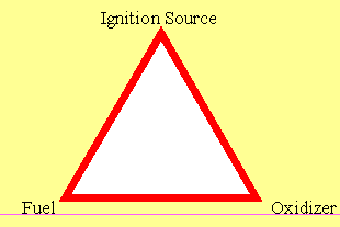
In addition to this, two additional facets are required; something to mix the fuel and the oxidizer (such as the turbulence created in a gas leak under pressure) and containment. It is however common industrial practice to use the term 'explosion' for both confined and unconfined combustion.
For any mixture of a combustible gas or vapor with an oxidizer there is a critical ignition energy. If one releases less than that critical amount of energy into the mixture, there will not be a self-propagating explosion. Some combustion may occur transiently, but the combustion wave will not grow and become self-propagating. If one releases at least the critical amount of energy, the combustion wave will pass through the incipient stages of growth and become self-propagating as a plane wave, resulting in an explosion.
At a critical concentration called the most easily ignited concentration (MEIC), the amount of energy required to cause ignition is minimal. If the ignition experiment is conducted under conditions where it is assumed that all the energy injected into the gas/vapor cloud is used in the combustion process, the critical energy at the MEIC is called minimum ignition energy (MIE). As the concentration is varied from the most easily ignited concentration the amount of energy required to cause ignition increases, until at certain points, the mixture is no longer explosive. These points (derived by experiment) are referred to as the lower explosive limit (or LEL) at the lower concentration limit, and the upper explosive limit (or UEL) at the higher concentration limit.
The LEL and UEL are not inherent properties of a combustible mixture. Their values depend on the nature of the experiment by which they are determined, especially the size of the vessel and the energy available from the ignition source. No prudent person controlling concentration to reduce the risk of an explosion would operate much higher than 50% of the LEL except under very carefully controlled conditions. In most situations the limit is set at 25% or lower.
Effects of Oxygen Enhancement, Temperature, and Pressure
Oxygen enrichment increases the heat release within the combustion zone of the developing wave-front and therefore decreases the required initial energy contribution from the ignition source. The most easily ignited concentration of oxygen and vapors or gases ignites at about one hundredth the minimum ignition energy of the most easily ignited concentration of the same vapor or gas in air. Because the flame speeds are considerably higher, the pressure rise in an explosion-proof enclosure may also be much higher. No means of explosion protection considered safe for atmospheric mixtures should be considered safe in oxygen enriched mixtures without careful examination.
The qualitative effect of increasing temperature is relatively easy to estimate. Every material has a spontaneous ignition temperature, SIT (or AIT, autogenous ignition temperature) at which it will ignite spontaneously. Obviously, if the temperature of a mixture is raised, the amount of electrical energy required will decrease, reaching zero at the AIT.
The effect of pressure is understandable if one considers that when pressure increases the number of molecules per unit volume increases. The heat release per unit volume will consequently increase, and the ignition energy required to cause the incipient flame sphere to grow to its critical diameter decreases. Similarly, decreasing pressure decreases the amount of energy released in the combustion zone and increases the required electrical ignition energy. This relationship has been verified experimentally over many atmospheres of pressure change. Doubling the pressure of a gas cuts the ignition energy to approximately 25% of its former value.
Historical Background of explosion protection
The first hazardous area was discovered in the early coal mines. This area held a double hazard: methane gas (firedamp) and coal dust. Methane gas is absorbed in the pores of coal. When the coal is mined the methane is evolved, a process that takes a relatively short time. To be completely free of methane, coal has to be store for a period of up to 1000 hours.
When miners worked an 8-hour shift pattern, the mined coal would be left in the shaft until the next day, during which time the methane would start to be evolved into the air in the shaft. The methane would collect in pockets at the roof of the mine and form an explosive layer. The miners returning for the next shift would carry with them the means of igniting the gas, hat mounted candles, and hand carried oil lanterns. The resulting ignition of the methane would in itself not necessarily be fatal for the miners. It was the secondary ignition of coal dust, throw up into a cloud by the methane explosion, that resulted in a more violent and deadly detonation.
The first method used to remove the methane hazard was to have a person crawl along the mine floor holding a lighted torch in their outstretched hand. This procedure would 'safely!' ignite the methane layer and burn it off before the miners started work. The person performing this task was known as the 'fireman' and it was soon found that there were very few volunteers for this hazardous job. This resulted in prisoners being offered short jail terms if they would volunteer for the position.
With the advent of forced ventilation in the mines, the hazards were reduced by the dilution of the methane with fresh air so that it was below its explosive limit. When electrical equipment was first introduced into the mines, there were some explosions due to electrical sparking. However, it was discovered that totally enclosed motors were able to contain explosions without transmitting it to the surrounding external atmosphere. This concept was transferred to the design of other electrical equipment; fitting it inside substantial cast iron enclosures with tight fitting joints.
Later, low voltage signalling bells were introduced into the mines. It was believed that, since these bells operated on a very low voltage (12V or less), they would be safe. However, in the years 1912 and 1913, there were two disastrous mine explosions in England, which were traced to the signalling bells. Research showed (Mines Research Establishment, Buxton, England) that these low voltage circuits were capable of igniting mine gases, it also lead to new circuit designs in which the stored energy was reduced to a non ignition capable level. This technique was labelled 'intrinsic safety' and it was the beginning of a new era in safety methods for explosive hazardous areas.
Definitions and Codes
A hazardous area is defined as an area in which explosive atmospheres, or may be expected to be, present in quantities such as to require special precaution for the construction and use of electrical equipment. An explosive atmosphere consists of a mixture of flammable substances with air in the form of GAS, VAPOUR OR MIST in such proportions that it can be exploded by excessive TEMPERATURES, ARCS OR SPARKS. The gases, vapours or mists will only explode when mixed with air between specific percentage mixtures, these are called:
- LOWER EXPLOSIVE LIMIT (LEL)
- UPPER EXPLOSIVE LIMIT (UEL)
These mixtures will also have different: auto-ignition temperatures (AIT); minimum ignition currents (MIC - intrinsic safety test apparatus); maximum experimental safe gaps (MESG - relates to flameproof enclosures flame path), depending upon the substances contained within the mixture.

It is evident from the limited list shown in the table above that there are some natural groupings for the gases based on their MESG and MIC values. These groups are divided into two groups;
- Group I for mines susceptible to methane.
- Group II for explosive gases for locations other than mines; group II is further divided into three sub groups:
- IIA, for atmospheres containing propane or gases of an equivalent hazard.
- IIB, for atmospheres containing ethylene or gases of an equivalent hazard.
- IIC, for atmospheres containing hydrogen or gases of an equivalent hazard.
The natural grouping of the gases based upon the MESG and MIC values does not bear any relationship to the auto-ignition temperatures (AIT) of the various substances.
The auto-ignition temperature is the temperature, in øC, at which a gas will ignite spontaneously without another source of ignition. Because these temperatures do not correspond with the above groupings, a temperature code was established. The resulting temperature codes for the substances listed above (temperature classification) are shown in the table below.
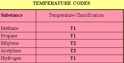
The full list of temperature codes are listed in the table below:
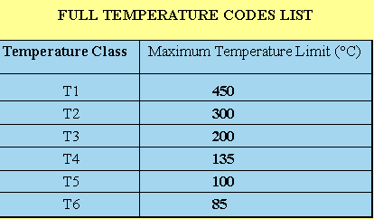
The gas groupings and the temperature codes are reflected in the markings that appear on electrical equipment, which has been certified for use in a hazardous area. The marking of the gas grouping and temperature code on the equipment identifies to the user the type of explosive atmosphere in which it can be safely installed (see Section 4 for further details).
Hazardous areas are further divided in zones, these zones relate to the predicted occurrence of when an explosive atmosphere may be present in the area. These zones are defined as being:
- ZONE 0, where an explosive atmosphere is continuously present, or present for long periods.
- ZONE 1, where an explosive atmosphere is likely to occur in normal operation.
- ZONE 2, where an explosive atmosphere is not likely to occur in normal operation and if it does occur it will exist only for a short time.
Commonly recognised concepts of protection
There are eight commonly recognised concepts of protection within Europe. These are detailed in the European EN50 series of Standards; 'electrical equipment for use in explosive atmospheres'. These methods of protection have, over the years, been added to and expanded to satisfy the new equipment designs that have appeared.
- FLAMEPROOF
- Intrinsically Safety - Apparatus or System
- PRESSURISATION
- INCREASED SAFETY
- Type N Protection (Non-sparking)
- OIL IMMERSION
- POWDER/SAND FILLING
- ENCAPSULATION
Electrical Equipment Marking
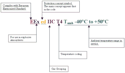
The electrical equipment that has been assessed and tested and, found to be in compliance with the relevant European Harmonised Standard is marked with the certification coding as described in the aforementioned standards.
CERTIFICATION CODING EXAMPLE
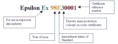
The marking details will also include the certificate number issued by the certification body.
CERTIFICATE NUMBER EXAMPLE
The equipment marking, assuming full compliance with the relevant standard/s is met, will also include the Hexagon Ex symbol, the affixing of this symbol enables the equipment to be sold and installed freely within Europe.
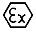
Hexagon Ex Symbol.
As was previously stated in the 'ATEX' article, the equipment will need to be ATEX certified from July 1st 2003 in order to carry the 'CE Mark'. If you want to place a mechanical or electrical product on the market in Europe after this date that is designed to be used in a potentially explosive dust or gas atmosphere, the ATEX Directive will be mandatory by law. The basic concepts and marking covered in this article remain, but there are many additional and more stringent safety requirements and additional marking requirements. Prudent manufacturers will begin assess if there product may be used in potentially explosive atmospheres (oil, gas, petrochemical, process, grain or food processing industries etc.) and begin the ATEX certification process now.
Sean Clarke is a specialist ATEX Compliance Engineer with Epsilon Limited, a company who design, test assess and certify equipment for the CE marking and Potentially Explosive Atmosphere certification including the ATEX Directive. Epsilon also offers training for both users and manufacturers of potentially explosive atmospheres equipment. Readers may contact Mr Clarke at the address below for further information or to arrange a free technical meeting.
Epsilon Limited: Tel 01244 541551 Fax 01244 543888 http://www.epsilon-ltd.com
Archive Index
EMC Journal Home

© Nutwood UK Ltd 2001
|
Eddystone Court - De Lank Lane
St Breward - BODMIN - PL30 4NQ
Tel: +44 (0)1208 851530 - Fax: +44 (0)1208 850871
nutwooduk@nutwood.eu.com
|
|


