|
EMC testing Part 4 – Radiated immunity
By Eur Ing Keith Armstrong C.Eng MIEE MIEEE, Partner, Cherry Clough Consultants, Associate of EMC-UK Tim Williams C.Eng MIEE, Director, Elmac Services, Associate of EMC-UK
This is the fourth in a series of seven bi-monthly articles on ‘do-it-yourself’ electromagnetic compatibility (EMC) testing techniques for apparatus covered by the European EMC directive. This series will cover the whole range of test methods – from simple tests for development and fault-finding purposes, through lowest-cost EMC checks; ‘pre-compliance’ testing with various degrees of accuracy, on-site testing for large systems and installations; to full-specification compliance testing capable of meeting the requirements of national test accreditation bodies. Previous articles in this series are available on-line at www.compliance-club.com, using the site’s Archive Search facility.
What is low-cost to an organisation of 5000 people could be thought fairly expensive by a company of 50, and might be too expensive for a one-person outfit, but we will cover the complete range of possible costs here so that no-one is left out. Remember though, that the more you want to save money on EMC testing, or reduce the likelihood of being found selling non-compliant products, the cleverer and more skilled you need to be. Low cost, low risk and low EMC skills do not go together.
This series does not cover management and legal issues (e.g. how much testing should one do to ensure compliance with the EMC Directive). Neither does it describe how to actually perform EMC tests in sufficient detail. Much more information is available from the test standards themselves and from the references provided at the end of these articles.
The topics which will be covered in these seven articles are:
1) Radiated emissions 2) Conducted emissions 3) Fast transient burst, surge, electrostatic
discharge 4) Radiated immunity 5) Conducted immunity 6) Low frequency magnetic fields emissions and
immunity; plus mains dips, dropouts, interruptions, sags, brownouts and
swells 7) Emissions of mains harmonic currents, voltage
fluctuations, flicker and inrush currents; and miscellaneous other tests
Table of contents for this Part
4 Radiated RF immunity 4.1 Saving costs by early EMC testing 4.2 Immunity testing for reliability and functional safety 4.3 Introduction to radiated field testing and its main issues 4.3.1 Preventing leakage and ensuring field uniformity 4.3.2 The high (and non-linear) sensitivity of analogue and digital circuits to RF fields 4.3.3 Using modulated RF waveforms 4.3.4 Determining an ‘engineering margin’ 4.3.5 Performance criteria and making functional measurements during the tests 4.4 Alternative test methods 4.4.1 Close-field probes 4.4.2 Voltage injection probe 4.4.3 ‘Crosstalk’ injection techniques 4.4.4 Licensed radio transmitters 4.4.5 Conducted test methods 4.4.6 Striplines (TEM devices) 4.4.7 Test cells and compact chambers 4.4.8 Using the IEC 801-3 test method 4.4.9 Mode-stirred chambers 4.5 Correlating alternative test methods with EN 61000-4-3 4.8 References
4 Radiated RF immunity
Part 0 of this series [1] described the various types of EMC tests that could be carried out, including:
· Development testing and diagnostics (to save time and money) · Pre-compliance testing (to save time and money) · Full compliance testing · ‘Troubleshooting’ to quickly identify and fix problems with compliance tests. · QA testing (to ensure continuing compliance in volume manufacture) · Testing of changes and variants (to ensure continuing compliance).
And Part 0 also described how to get the best value when using a third-party test laboratory [1].
This part of the series focuses on testing radiated radio-frequency (RF) immunity, sometimes called radiated electromagnetic susceptibility (EMS) to the EN standards for typical domestic / commercial / industrial environments. Other kinds of immunity tests may be required by the EMC standards for automotive, aerospace, space, rail, marine and military environments. These industries have over the years developed their own test standards based on their own particular kinds of disturbances, usually for reliability reasons.
Important Safety Note: Some of these tests involve electrical hazards, particularly the outputs from RF power amplifiers and antennas connected to them. Also, performing these tests without a shielded room can create serious interference problems for other equipment, possibly interfering with aircraft communications, navigational radio beacons, or automatic landing systems so can have safety implications. These tests can be dangerous, and all appropriate safety precautions must be taken. If you don’t know what safety precautions to take, ask a competent person.
The basic EN test methods described here are usually identical to the basic IEC test methods (e.g. EN 61000-4-3 = IEC 61000-4-3), so this article may also be of use where non-EU EMC requirements apply.
4.1 Saving costs by early EMC testing
As for close-field radiated emissions testing [1], not all the areas which cause significant responses on a close-field or direct injection RF immunity test may cause test failures when the final product is tested ‘properly’. Also, some of the areas that appear to be less sensitive to a close-field test may turn out to be the most sensitive on a proper product test. So using these close-field immunity techniques to make printed circuit assemblies more robust to RF fields can sometimes result in over-engineering.
However, with today’s fast moving markets a product’s time-to-market is generally more important for financial success than achieving the lowest material cost [2] – although many project managers appear to be lagging in their understanding of this basic modern fact.
Dealing with potential compliance problems at the earliest possible stages in product design and development can give a large competitive advantage by preventing the delays and redesign that usually follow a failure to pass compliance tests (when the product is complete, the drawings have been issued to production, and the parts lists have been issued to the purchasing department, who have already bought several thousand sets of PCBs and their components). A moderate added cost in preventative measures that may not actually be needed is a small price to pay for saving even one iteration of EMC compliance tests.
Most of us have been in this situation at some time (often several times) and the modern message for management is that engineering does not need to be this stressful and wasteful to gain the maximum financial advantage from new products. When you as a designer are asked by a manager to prove that you really do need the EMC suppression component or PCB routing feature that you feel might be necessary to ease EMC compliance – then you know it is time to send your manager off for retraining.
4.2 Immunity testing for reliability and functional safety
The radiated immunity tests which are harmonised under the ECM directive are supposed to cover normal electromagnetic environments, but one thing they conspicuously do not cover is proximity to personal radio-communications, such as cellphones and walkie-talkies. In fact, the generic immunity standards are honest enough to state that they do not cover this situation. How tenable this is – now that almost everyone carries a cellphone (Figure 4A shows a common-enough situation) and many industrial workers carry a walkie-talkie (a private mobile radio handset) as well – is open to question.
Figure 4B shows some fairly crude estimates of the typical field strengths which can be expected from mobile phones. It is recommended that products are tested with field strengths similar to the RF fields at the frequencies of the mobile radio-communications they are likely to be exposed to in normal operation.
Where products (especially controls and control surfaces) can be closer to the antennas of mobile radio transmitters than the distances shown in Figure 4B, testing at their transmitting frequency to 30V/m, 100V/m, or even more may be required to ensure reliable operation.
Where it is desired to create reliable or functionally safe products, the EMC immunity work done should go beyond the standard EMC directive immunity tests:
· Determine the normal and low-probability exposure of the product to electromagnetic disturbances of all types. Chapter 4 of [3] has some useful tables and other information that can help here. · Determine the susceptibility of all the critical functions to these disturbances, and the consequences of the functional degradations for reliability and safety. · Decide how far to go in ‘EMC hardening’ the product or system to improve the reliability and/or safety to acceptable levels. · Design and test the product or system accordingly.
The financial rewards of producing reliable products can be very great indeed, as one UK manufacturer discovered when they spent £100,000 on redesigning their products to comply with just the ordinary EMC directive immunity standards, and found that as a direct result their warranty costs fell by £2.7 million/year.
Increasingly, sophisticated electronic products or systems are used in areas where functional errors or failures can be very costly or can cause injury or death – but these are not covered at all by harmonised standards under the LVD or EMC directives, which often specifically exclude such issues. The Machinery, Automotive EMC, and Medical Devices directives and their harmonised standards do make some attempt to cover these issues, but fail to address them correctly [4].
Refer to the IEE Guidelines on EMC and Functional Safety [5], and articles on it [4], [6], [7], IEC 61508-2 [8] and IEC/TS 61000-1-2 [9] for more on these increasingly vital issues. These issues should be covered to be able to help make a ‘development risks’ defence under the Product Liability directive, and standards closely related to [8] and [9] are likely to become mandatory in the EU under safety directives in a few years time.
4.3 Introduction to radiated field testing and its main issues
There are five big issues in radiated RF immunity testing which are of concern for all the test methods, not just to EN 61000-4-3:
· Preventing the test radiated field from ‘leaking’ and interfering with other equipment. · Exposing the equipment under test (EUT) to a reasonably uniform electromagnetic field. · The high and non-linear sensitivity of analogue and digital circuits to RF fields. · Determining a reasonable ‘engineering margin’. · Monitoring the EUT to tell when its performance has degraded.
It will help if we discuss these issues before moving on to describe the test methods themselves.
4.3.1 Preventing leakage and ensuring field uniformity
Because quite an intense radiated field is created over a reasonable volume during this test, the field can travel far beyond the test area and so could possibly interfere with radio and TV broadcasts, or aircraft communications (for example). This possibility is prevented by performing radiated immunity tests in a shielded room.
Unfortunately, the reflections from the walls, ceiling and floor in a plain shielded room create problems for field uniformity. This is usually dealt with by lining the metal surfaces inside the room with RF absorbing material. Various types of absorber are available, and the most usual types are carbon-loaded foam pyramids (which take up a lot of room) or ferrite tiles (which are heavy). Both types of absorber are very expensive compared with the cost of the plain metal shielded room.
The correct, fully compliant test method for 80-1,000MHz is described in detail later in this article. In essence, it requires calibrating an anechoic chamber by transmitting RF fields inside it from the test antenna, measuring the field in Volts/metre (V/m) at specified points in the chamber (the ‘test volume’) to establish whether the field meets the criteria for uniformity. A table is created of the signal level required at each test frequency to achieve the required field strength when averaged over the test volume. The EUT is not present during this chamber calibration, but even so the field levels over the test volume are allowed to vary by +6dB, -0dB from the nominal.
EUTs are tested by placing in the test volume in the chamber, with the transmitting antenna in the same position as for the calibration, then ‘replaying’ the file of signal levels into the antenna. Of course, the actual field levels created during a test are modified by the EUT and its cables and can vary significantly – often more than ±15dB – from place to place near the EUT due to reflections, cable resonances, etc., but this is just the sort of thing that happens when an EUT is placed in an RF field in real life.
An anechoic chamber (see Figure 4C) has absorber on the floor, unlike a semi-anechoic chamber which has a metal ground-plane floor. Some test laboratories use semi-anechoic chambers as ‘indoor OATS’ (Open Area Test Sites) for measuring emissions, dragging in as much absorber to cover the floor as is needed to convert the chamber to anechoic and achieve the EN 61000-4-3 field uniformity.
Figure 4C
Some testers use an anechoic chamber for both radiated RF immunity and emissions, thereby avoiding the height scan required when doing emissions tests with a ground plane (mentioned in section 1.10 of [1]). Such an emissions test is not a compliant test, but most companies find that they get very good correlation with a fully compliant OATS test if they add 6dB to their anechoic emissions results.
If you want to build your own anechoic chamber, read [10]. This deals with the absorber in some depth – but does not tell you how to create a well-shielded room in the first place.
4.3.2 The high (and non-linear) sensitivity of analogue and digital circuits to RF fields
The problems of test repeatability would be bad enough if electronic circuits responded linearly to variations in the fields, but they respond non-linearly and so even small variations in the field level or the set-up of the EUT and its cables can make the difference between a good pass and a bad fail.
As was mentioned in section 1.2.2 of [11] all semiconductors happily demodulate radio frequencies – whether they are digital or analogue – and no matter what their functions are (even ‘slow’ operational amplifiers). In this respect all semiconductors act just like the RF detector in a ‘crystal radio set’ and will demodulate whatever RF signals they are presented with by their ‘antennas’.
Investigating the amplitude response of a circuit to varying RF fields first (ignoring ‘antennas’ by assuming that the set-up of the EUT and cables is unchanged) we find that analogue circuits usually respond to RF fields with the square-law relationship typical of demodulation. For example, increasing the field strength by 6dB often causes a 12dB increase in signal error. So even small variations in the field distribution, and/or small variations in the number of cables and their layout, can make very large differences in EUT response. For example, if an analogue function of the EUT is 6dB under its performance criterion it has passed the test by what seems to be a good margin – but an increase in the field strength of 5dB near one of its cables could cause the signal error to increase by 10dB, making the function 4dB over its performance criterion. Alternatively, a fail by 3dB might be turned into a pass with a 5dB margin if a cable or part of the EUT is exposed to a 4dB lower field strength.
Digital signals can present even greater functional variations when field strengths change. The semiconductors in digital ICs demodulate the RF in a square-law fashion as for analogue circuits, but the digital circuits ignore noise that is below its thresholds. So a product can pass a radiated test even though the interference levels in the logic circuitry from the RF fields are mere millivolts under the thresholds. A small increase in the RF field strength (say, by just 1dB) could cause the digital circuit to behave erroneously, which in many circuit and software designs can cause a ‘fatal’ error or a ‘crash’. Alternatively, a small decrease (say, by -1dB) in the field strength near part of the product or its cables could convert a fail into a pass. Some poorly-realised digital circuits operate with software-dependant internal noise levels (e.g. due to ground bounce) which are already close to the logic thresholds, so don’t need much additional noise from demodulation to push them over the threshold and cause an erroneous logic state. Digital circuit errors that depend upon software and interference often appear in the field as if they were random events, which can make them very hard to diagnose and fix.
Many modern digital ICs and communications are now operating with very low supply voltages (e.g. 1.8V) and/or very low signal swings (e.g. LVDS). For these types of circuits the logic thresholds may be a mere few hundred millivolts, not volts, making their circuits much more vulnerable than the 5V logic they replace.
Figure 4D shows an example of the typical effect of a 6dB increase in field strength on both analogue and digital circuits (all else remaining the same).
Now we need to investigate what it is that feeds the RF signals into our semiconductors – where do the ‘crystal radio set’ antennas come from? For most electronic products these ‘antennas’ are accidental. They include integrated circuit lead frames, PCB traces and cables, which all have natural RF resonant frequencies set by their lengths, shape, dielectrics (e.g. insulation), source and load impedances, and proximity to other conductors and dielectrics. At higher frequencies than 1GHz even bond wires can be significant antennas. Figure 4E shows how idealised real-life PCB traces and cables resonate.
The result is that from a radiated RF immunity point of view, all electronics can be viewed as a huge number of very broadband demodulators (crystal radio sets, several million in some modern ICs) connected to a very large number of accidental ‘antennae’ each tuned very efficiently at multiple resonant frequencies.
When we measure a product or system for RF immunity we often find a series of frequencies at which the response of the EUT is much worse than other frequencies. It is usually possible to relate these frequencies to the length of an interconnecting cable, the diameter of a looped cable, the length of a PCB trace, or the size and shape of metalwork, and such observations often allow the problem to be identified and fixed quickly. Figure 4F shows a real-life example of the ‘crystal radio set’ behaviour of a slow type of opamp.
(Sometimes we find a broad band of frequencies over which the EUT has a strong response to the RF field, but after a few remedial EMC measures have been applied such EUTs tend to be more like most of the others in just having peaks in their responses at various frequencies.)
The problem is that these ‘peaky’ responses are often only a few tens of MHz wide, and many are totally dependant on cable length and route. Just moving a cable by a few centimetres can move the frequency they are ‘tuned’ to by tens of MHz, an effect that anyone who is experienced with testing radiated immunity (or radiated emissions) will be very familiar with. Changing a 2 metre cable to a 3 metre one can shift a number of immunity peak responses so that the immunity ‘signature’ of the EUT becomes completely different. Figure 4G shows an example of how small variations in the length of a nominally 1.5 metre cable can effect its ‘antenna effect’ and hence the susceptibility of the EUT.
4.3.3 Using modulated RF waveforms
EN 50082-1:1992, the generic immunity standard has been widely used for many years. It used the IEC 801-3 test method (see later) and unmodulated RF fields, despite the fact that most intentional radio transmissions are modulated.
Happily, EN 50082-1 is now ancient history and almost all electrical products supplied in the EU must now meet the generic standards EN 50082-1:1997 or EN 50082-2:1995, or a host of product-family immunity standards – nearly all of which call up EN 61000-4-3 as their basic test method for radiated immunity – such as: EN 55024 (ITE and telecoms); EN 61326-1 (laboratory equipment); EN 55103-1:1997 (professional audio, video, lighting); EN 50130-4 (alarms and security); EN 55104-2 (household appliances). EN 55020 (broadcast radio and TV receivers and associated equipment) is an oddball standard which for historical reasons uses quite different methods to EN 61000-4-3; a common approach for these products is not yet on the cards.
EN 61000-4-3 uses modulated fields: a 1kHz sine-wave modulation with 80% depth, meaning that the peak level of a 3V/m field is 5.4V/m (18V/m for a 10V/m field). Because of the non-linear response of analogue and digital circuits due to demodulation an 80% increase in RF level can translate into a 224% increase in circuit error. So all the alternative test methods described below should use similarly modulated fields or test signals.
4.3.4 Determining an ‘engineering margin’
The EN 61000-4-3 test method cannot guarantee that a given EUT and its cables will be exposed to exactly the same distribution and levels of fields (say, within ±3dB) even on a repeat test in the same chamber with the same test gear, unless the set-up of the EUT and its cables is exactly replicated. But even exact replication of EUT and cable set-up in a different chamber cannot ensure a replication of the field distribution , unless the chamber and the transmit antenna and the RF power amplifier that drives it are themselves also physically identical. Alternative test methods to EN 61000-4-3 (e.g. GTEM cells) will not create anything like the same field distributions around an EUT and its cables as an anechoic chamber, and field errors can exceed ±20dB.
Because of the non-linear sensitivity of analogue and digital circuits to RF field level, and because products made in volume manufacture have variations in their immunity performance due to component and assembly tolerances (often uncontrolled as far as EMC is concerned), an ‘engineering margin’ is recommended for radiated immunity tests. Even when testing to EN 61000-4-3 in a fully compliant manner, at least a 6dB higher test level (e.g. 6V/m instead of 3V/m) is suggested, with the product still meeting its required functional specifications.
Where there are significant differences in the test method, even where the new method has good field uniformity (e.g. Striplines at low frequencies or GTEM cells), a much larger engineering margin is recommended.
It is clear that saving costs by using alternative radiated immunity test methods on the final product can lead to over-engineering. The additional cost to make the product pass the alternative test method with the necessary engineering margins should be weighed against the cost of doing the testing properly to EN 61000-4-3 with a mere 6dB engineering margin.
(Close-field and other alternative radiated immunity test methods which are more suited for use during design and development (e.g. on a prototype PCB assembly on an engineering bench) should still be done, even where the final product is going to be fully tested to EN 61000-4-3. They will help ensure that the final test is a formality and so reduce time-to-market, as discussed in 4.1.)
4.3.5 Performance criteria and making functional measurements during the tests The functional performance degradation allowed during and after radiated immunity tests may be specified by product-family standards (e.g. EN 55024), but if applying the generic standards EN 50081-2 or EN 50082-2 all that is necessary is that the performance is no worse than the specification in the manufacturers ‘data sheet’ for the product – which should represent what its users would find acceptable given the marketing claims for the product.
Because the tests must be done in a sealed chamber, and because people are not allowed to be inside the chamber during the tests, some thought should be given to how the functional performance of the product is to be tested.
Most test laboratories are equipped with shielded video cameras (see Figure 4H) and monitors so that the EUT’s displays can be watched from outside the chamber, but modifications may be needed to the EUTs software or hardware to provide the necessary diagnostics via the display. For example, it often happens that a microprocessor will crash but the display continues to show the same image – giving the impression that all is well and wasting expensive testing time.
So displays should always be changing in a way that shows that as much as possible is working correctly. Display change rate should preferably be in the order of twice per second, so that the ‘dwell time’ at each frequency can be less than one second and testing time is not made too long (and expensive).
Some products employ very long time constants, and it may be impractical to speed them up without changing their EMC characteristics, in which case lengthy testing times may be necessary. Where a product has multiple functions, a test could be done on each function in turn, or the functions may be able to be multiplexed quickly, so that all are tested in sequence during the dwell time at each frequency. Sometimes a product runs through a sequence of states or functions that can be speeded up to shorten radiated immunity test times, often by removing wait states from the software.
So it is quite common to create special product software for radiated immunity testing, to shorten the test time and reduce testing costs. Few test laboratories would challenge such software and would merely record the software version number in their test report. I have heard of some engineers who write this special software in such a way as to make the product appear to have greater immunity than it would if using the software it is supplied to users with. Cheating at the tests may enable a pass report to be obtained from a prestigious test laboratory, but leaves the product itself open to compliance challenges.
Where monitoring requires specialised test equipment, this should be placed outside the test chamber wherever possible so as not to test the monitoring equipment instead of the EUT. Audio distortion analysers (for example) are often so susceptible to RF interference that most of the remedial work during testing to EN61000-4-3 may be needed on the analyser and not on the EUT – even though the analyser is outside the test chamber where the fields are being generated. Most digital voltmeters and multimeters are also very susceptible, so it may be worthwhile hanging on to those old electronics-free moving-coil meters – even though they are not totally immune either.
Always suspect functional test instrumentation, which might show an fail result when one is not in fact present, or might show a pass when the EUT is failing. The usual way to deal with the latter issue is to set the EUT up in such a way that the functional test meter (or whatever) is indicating a non-zero quantity (if possible) and then watch it during the EUTs immunity testing for it to reduce or increase when it shouldn’t do either.
A problem with passing cables through a chamber wall to ancillary equipment or functional test instrumentation is that the bonding of the cable shield to the wall and any filtering applied to the signal conductors alters the termination of the cables from what would occur in real life. The effect of the chamber wall terminations and filters is to alter their resonant frequencies, but also to increase the amplitude of the cable resonances – both can lead to overtesting or undertesting. Most test laboratories simply ignore this issue, although some use rows of ferrite clamps rather than terminating the cable at the chamber wall. Richard Marshall Ltd (www.design-emc.co.uk)have developed a 150W chamber exit filter intended to overcome this problem [12].
Because of the problems of monitoring EUT parameters with conventional instruments during immunity testing, especially when trying to measure circuit voltages or currents to troubleshoot a test failure, at least two manufacturers have developed tiny probes that are connected to external measuring gear (well away from the effects of the tests being applied) by fibre-optic cables. Two of these are described in references 6 and 7 to Part 3 of this series [14]. Tiny probes used by these types of systems have been developed for measuring voltage, current, and local field strengths, sometimes with bandwidths exceeding 1GHz.
Fibre-optic cables – providing they are completely metal-free – can simply be passed through a waveguide-below-cutoff tube set in the wall of the chamber without compromising the test or causing chamber leakage.
4.4 Alternative test methods
Alternative radiated RF immunity test equipment and methods can be used for all the test purposes listed in the introduction. The EN 61000-4-3 test method is not suitable for design, development, or troubleshooting to solve compliance problems, so there is a very real need to use some of the alternative methods described here. Alternative test methods are not just a low-cost alternative to full-compliance tests, they have their own particular strengths as part of a commercially-successful company’s EMC activities.
Testing to EN 61000-4-3 is only cost-effective for QA and variant testing where a company has its own fully-compliant anechoic chamber located near to the people who need it (probably a fairly large company). Otherwise the alternative test methods come into their own, this time simply as low-cost or faster alternatives to the ‘proper’ test method.
When used for design and development purposes, and to help fix compliance problems, the lack of a calibration for alternative test methods is not very important. But it is necessary for the tests to be repeatable, so consistency is required in the test equipment and test methodology.
If using alternative methods to do remedial work after an immunity test failure, you will know which frequencies the product fails at and can test at only those frequencies to find the problem areas most quickly. However, when you make any changes to fix the known immunity problems you then need to test over the full frequency range, in case all you have done is ‘re-tuned’ the problems so they appear at different frequencies.
During design or development testing, always try to reproduce the final assembly of the circuit being tested (shielding, earth bonding, proximity to metal objects or structures, etc.), as the stray inductances and capacitances in the final build state can have a dominant effect on the RF behaviour of the circuit. And always carefully record all the details of the test set-up in the test documentation (photographs can be very useful).
Even where the alternative methods used are very different to EN 61000-4-3, always try to follow the EN 61000-4-3 methods as far as possible (refer to section 4.7). For example:
· Use RF fields or test signals that are 80% amplitude-modulated by a 1kHz sinewave. · Set the EUT and its cables up in according to EN 61000-4-3 (as far as possible). · Establish the most susceptible set-up for testing.
Alternative test methods such as TEM cells are mentioned in EN 61000-4-3, and can be used for full compliance testing if equivalence with the anechoic method (described in 4.7 below) is established. But demonstrating equivalence is very difficult indeed, not least because of the non-linear responses of semiconductors to RF fields described in 4.3.2.
4.4.1 Close-field probes
The close-field magnetic and electric field probes as described in [1] can be used as localised sources of disturbances in immunity tests, and are very useful indeed for design and development testing on ICs and PCBs, and for localising the immunity problems discovered on a ‘proper’ immunity test.
While the home-made probes in [1] should be robust enough to survive being used in immunity tests, if you are using purchased probes check that they are capable of handling the proposed use before using them. If purchased probes get hot when used for immunity testing, stop using them immediately. Some probes contain baluns and these are often be the limiting factor for power handling.
The close-field magnetic and electric field probes shown in Figures 1, 2 and 4 of [1] can be connected directly to the output of an RF signal generator, or to the output of an RF power amplifier used to boost the signal generator. Some amplifiers intended for EMC testing use are very forgiving of their load impedance, but most other types of RF amplifiers can be damaged by a mis-matched load. For these latter amplifiers a 50W resistor should be used to terminate the probe (in series with a loop probe, in parallel with an E-field probe), making sure that the termination uses RF techniques to remain a good 50W up to the highest frequency required. If an RF amplifier is needed, one rated at 1W or 2W over the whole frequency band is usually sufficient for close-field probe tests. Low-cost wide-band amplifier modules from Mini-Circuits (www.minicircuits.com) are often quite adequate.
The probes will generate localised magnetic or electric fields, or magnetic and electric fields simultaneously for those of Figure 4 of [1]. The procedure for using the probes is similar to that used for detecting localised sources of emissions – the probe is scanned carefully over the suspect areas of the product, very close to any devices or conductors, until the most sensitive areas are located. You soon get to know which part of the probe emits the strongest fields, and in which direction they are emitted, and with a 10mm loop probe it has been possible to locate an RF sensitive area on a PCB to within 2mm.
It is usual to start off with a low signal level set on the RF generator, increasing the level until significant responses are discovered, fixing those, and then increasing the test level until the next batch of less-sensitive areas are discovered. The signals for the RF generator can be either continuous-wave or modulated. Because all EU EMC compliance tests now use modulated fields, modulated waveforms (using the actual modulation type specified in the standard for the final product) are generally recommended.
4.4.2 Voltage injection probe
‘Pin’ probes like the one shown in Figure 2 of [1] can be used to inject RF signals directly into conductors and component leads, and are useful for design and development testing on ICs and PCBs, and identifying the locations of problems that cause compliance test failures.
They will need to use a high-voltage Class Y capacitor when injecting into mains or other high voltages. Use a 10nF capacitor for frequencies up to 100MHz, and 1nF for up to 1GHz. If the load that this adds affects the circuit’s operation, smaller capacitors should be used (say, 10 or 100pF) although these may require a higher RF drive voltage at lower frequencies.
The output from a signal generator will normally be sufficient to drive a direct injection probe at levels equivalent to very high RF fields, but where such a probe is driven from an RF power amplifier, an RF termination resistor may be needed as described in 4.4.1. Take care not to drive sensitive circuit nodes so hard that they are physically damaged, unless this is an intentional part of the test.
When using the probe to inject into the mains or other high-voltage circuits, there will be an initial pulse of current as the capacitor charges when first connected. Take appropriate steps to make sure that this does not damage the RF source.
4.4.3 ‘Crosstalk’ injection techniques
Another way to inject RF into products – useful for design, development, and diagnostic purposes – is to power a length of wire from a signal generator directly or boosted by an RF power amplifier (an RF termination resistor may be needed, as described in 4.4.1). This RF energised wire can be laid close to other wires, or PCB traces, and will couple RF energy into them by ‘crosstalk’. Wire injection will start to behave very unpredictably when the length of the wire is longer than one-twentieth of the energising signal’s wavelength, so shorter pieces of wire will be needed to test at higher frequencies.
The capacitive clamp used for fast transient burst testing to EN 61000-4-4 could also be connected to the output of an RF power amplifier and used to simulate the coupling of RF fields with cables. It would need to have a suitable RF termination to the ground plane.
4.4.4 Licensed radio transmitters
Most radio amateurs have at least one licensed transmitter operating in certain frequency bands, and it is usually fairly easy to borrow 900MHz and 1800MHz cellphones from colleagues and neighbours. If you can get a tri-band cellphone it will generate around 900MHz, 1800MHz, and 1900MHz (although it is probably illegal to use the 1900MHz frequencies in the EU, or the 900/1800MHz in the USA). Where a product or system is going to be used at a location where a private mobile radio system is used, handsets can often be borrowed.
Where vehicular mobile transmissions may be a problem, you may be able to take your product to the local police, ambulance, or fire stations, or even have them visit you (no false alarms, please!). I know of one very small company making specialist audio equipment who takes each of their hand-crafted products to a number of remote transmitter sites (AM, FM, TV, etc.), gets as close to the antennas as the side-roads and perimeter fences allow then operate their products with appropriate cables attached from a portable generator, on the basis that “If it works OK in these environments it is probably going to be OK anywhere else” – which is not in fact correct, as will be explained.
Using legal transmitters to test the RF immunity of a product or system is, of course, quite legal. When using amateur radio or private mobile radio channels be courteous to other users by avoiding the channels that are already in use, and by limiting the time spent transmitting on an unused channel to under 1 minute. No such time limitations apply to cellphones. All transmitters should be in transmit mode, and for cellphones and possibly some other radio systems this means that a call has to be successfully made, which means that you need to have someone to phone up. It is a good idea to use your radiated emissions measuring equipment (see [1]) to check that the radio transmitter actually is transmitting with the sorts of frequency and power levels expected.
Figure 4B gives some idea of the distances that some mobile transmitters need to be to create fields of 3 and 10V/m, but a general rule of thumb is that the electric field in V/m equals Ö(ERP) · 5.5/d, where ERP is the equivalent radiated power in Watts and d is the distance from the antenna in metres. This rule only works where there are no reflective objects or surfaces nearby (ideally in an anechoic chamber) and it does not work at all close to the antenna – say closer than 3 antenna-lengths. For an omni-directional antenna like the whips used by most handsets ERP = total radiated power.
Testing with licensed radio transmitters seems a reasonable thing to do where a product or system may actually be exposed to those radio transmitters in real life. Since the EN 61000-4-3 tests don’t test above 1GHz (at present) it also seems like a good idea to operate some 1800MHz cellphones in close proximity and see what happens.
Unfortunately there is a very serious limitation to testing with licensed radio transmitters – a small change to a cable route can invalidate the result, as was described in detail in 4.3.2 and shown in Figure 4G.
So the best results can be had from licensed radio transmitter testing if multiple tests are done for each radio channel, with a large number of different cable set-ups, including different cable routes, different types of cables and connectors, different numbers of cables, a wide variety of accessories – plus different heights of the EUT above the ground, different proximities to other equipment and metal structures, different internal build options (if there are any) such as alternative power supply modules, etc. Only by doing such tests can any correlation with EN 61000-4-3 be achieved, and then only for a few tens of MHz either side of the licensed radio channels used.
So the only time that testing with licensed radio transmitters can provide hard evidence of immunity to the radio frequencies found in its operating environment, is when the tests are done on a finished installation where the product and all its cables are fixed in position and can’t be moved.
But as the product and its installation ages, its shielding and electrical bonds degrade, so retesting with the same transmitters is necessary to make sure that it hasn’t become susceptible. The slightest alteration to the installation – even merely moving a cable – means retesting with the transmitters again to make sure it is still immune enough. This is one reason why all mobile radio transmitters and cellphones are banned from many larger computer rooms – what was immune to a mobile phone handset yesterday isn’t guaranteed to be immune tomorrow. Where a malfunction in a computer could cause a safety hazard or large financial losses, it is necessary to question how sure you can be that people won’t forget about the ban, or ignore it when problems don’t seem to arise. If the consequences of a computer failure are very great, you may need to employ security guards with the authority to enforce the rule, and they may need to search everyone who enters.
4.4.5 Conducted test methods
IEC 61000-4-6 is used for full-compliance conducted RF immunity testing of cables from 150kHz to 80MHz and – if the EUT is small enough – up to 230MHz (as will be described in detail in Part 5 of this Series, in the next issue).
It uses a variety of injection transducers:
· A variety of Coupling-Decoupling Networks (CDNs) for direct voltage injection into cables. There are many designs of CDN to suit the many different kinds of cables and the different power and signals they may be carrying. · The EM-Clamp, which simply clips over a cable (or cable bundle) and injects via a current transformer and simultaneously via the small capacitance. The EM-Clamp is long because it includes a row of ferrite absorbers to reduce the exposure of the ancillary equipment to the test. This means it must be used the correct way around. · Bulk Current Injection (BCI), which uses clip-on current transducers. BCI has been a favourite technique of the military and automotive industries for many years, and appears as a formal test method in some of their EMC standards, e.g. DEF STAN 59-41 Part 3 test DCS02 (available free from http://www.dstan.mod.uk/home.htm) and ISO 11452-4:1995 respectively.
The conducted methods described in EN 61000-4-6, and similar conducted methods, can be used as an alternative to radiated emissions testing at 80MHz and above. Some suppliers offer CDNs which operate to 500MHz, and some BCI clamps will operate to 400MHz. Although it is possible to use conducted techniques to such high frequencies, at frequencies for which any dimensions of the EUT become comparable with (or larger than) their wavelength, any correlation between conducted and radiated test methods degrades very quickly.
Part 5 of this series will have a detailed description of testing to EN 61000-4-6, and alternative test methods for conducted RF immunity, so it will not be described in detail here.
The cables into which RF currents are injected can act as antennas and radiated RF fields into the environment, possibly causing an interference nuisance. So it is recommended that BCI testing is done in a shielded room with the door shut.
4.4.6 Striplines (TEM devices)
The stripline is another favourite of the Automotive industry, and is also specified by EN 55020 for testing radio broadcast receivers and the like. TEM stands for Transverse Electromagnetic Mode because the electric field is generated across the test volume, between two metal plates. Striplines generate fields with only one polarisation, and usually include a block to stand the EUT on so that it is in the position where the maximum field strengths are created. Three sets of tests are generally done, each with the EUT arranged in one of three orthogonal orientations.
It is easy to make your own low-cost stripline by following the construction details in Annex E of EN 55020. Figure 4J is an example of a proprietary stripline product that uses a higher impedance than the usual 50W so that its metal plates are narrower. This makes it more useful as a bench-testing device for the design and development laboratory because the stripline can relatively easily be rotated around the EUT to test with the field in the three orthogonal directions. The EUT and its cables do not have to be moved, improving test repeatability and saving time too.
In any stripline there is a preferred volume for the EUT and its cables that is smaller than the actual volume between the stripline plates. Usually the maximum height of the EUT is only one-third of the spacing between the stripline’s plates. There is no limit on the size of a stripline, as long as its shape is preserved (it is the ratio of the spacing of the plates to their width that preserves their characteristic impedance), and at low frequencies the field strength is simply the voltage between the plates divided by their spacing.
However, at frequencies for which the distance between the plates exceeds half a wavelength the resulting resonances will make the field strength between the plates vary greatly. Smaller-sized striplines work better at higher frequencies, but can only test smaller products. [15] describes how a standard automotive 150mm stripline was modified to generate 100V/m at up to 1GHz.
Large striplines can be used at frequencies beyond resonance, of course, but there will be a number of nodes and anti-nodes in the field between the plates and their locations will depend upon the frequency.
Striplines are usually terminated in their characteristic impedance (often 50W) so they generate both electric fields and magnetic. However, if they are terminated in a short-circuit they generate magnetic fields only (although only up to a lower frequency, because the transmission line is badly mismatched). This can be a useful feature, just as it can be useful to have individual magnetic and electric close-field probes, by helping to track down what exactly is the cause of a test failure.
Striplines should be operated inside a shielded room, because the field ‘leakage’ at their sides can be capable of causing an interference nuisance, especially when testing with high field strengths or above the resonant frequency of the stripline. Actually enclosing a stripline in a shield can create a number of types of immunity ‘test cell’, some of which are described in the next section.
A characteristic of striplines (and TEM cells in general) is that the layout of the cables associated with an EUT can make a great deal of difference to the test results. This is very important during remedial work, where the effects of modifying the product can be completely overwhelmed by the changes created if the EUT and its cables are not put back in exactly the same positions as for the unmodified test.
4.4.7 Test cells and compact chambers
A large number of compact chambers and ‘test cells’ have been developed by several companies as a way of making radiated immunity testing available at a more reasonable price, anechoic chambers being so expensive. Now that anechoic chambers are available for about half the price that they were five years ago (mostly due to reductions in the prices of absorbers) the economic argument for using these alternative cells is weakened – although many smaller companies will still find £50,000 a little on the steep side.
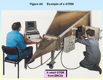
GTEMs
GTEM stands for Gigahertz Transverse Electromagnetic Mode, indicating that it is a development of the stripline which is useable to 1GHz or more. It uses a long tapered shape instead of parallel plates and an absorbing wall at the large end of the taper, all enclosed in a shielded box with the characteristic shape seen in Figure 4K. GTEMs are quite large devices, even though the useable area for the EUT and its cables is quite small, and like all TEM cells the layout of the EUT cables can make a great deal of difference to the test results.
Figure 4K
The idea is that a plane wave is launched from the narrow end of the taper and progresses down the cell, to be absorbed at the far end without reflection or distortion. In practice many very complex modes exist but nevertheless the GTEM has a good pedigree for doing radiated immunity tests in place of the full EN 61000-4-3 anechoic method. Interesting material on GTEMs can be found at the website of one of their inventors, Dr Diethard Hansen: www.euro-emc-service.de.
GTEMs are used for radiated emissions testing as well as immunity. They continue to develop, with some recent offerings able to rotate around the EUT to save test time.
Other test cells
Some test cells, like the Crawford cell, are just boxed striplines using various techniques to increase the useable volume for the EUT and its cables. Some compact chambers rely on integrating the transmitting antenna closely with the chamber itself to maximise field strength and field uniformity. Others, such as the GTEM, have developed so far from their original origins as a humble stripline or antenna in a metal box to become new branches on the evolutionary tree of EMC test equipment.
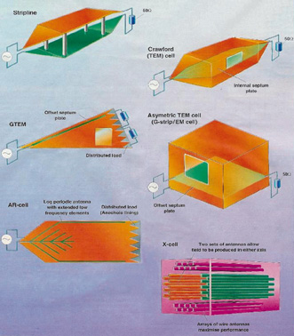
Figure 4L shows the basic internal details of six types of test cell or compact test chamber.
Figure 4L There are now many different types of test cell (Taken from “EMC Testing comes of age” Electronics Weekly, Sep 23 1998, page 26)
Clockwise from top left: Stripline; Crawford TEM cell; G-Strip/EM Cell; X-cell; AR-cell; GTEM Not shown: Laplace Instruments’ LaplaCell
The use of TEM cells of various types (including GTEM) for full compliance testing will be greatly aided when the proposed new standard EN 61000-4-20 is published, although it would take a few more number years after its publication before the generic and product-family immunity standards referenced it as a basic test method like EN 61000-4-3.
4.4.8 Using the IEC 801-3 test method
For several years, IEC 801-3 was the proper ‘full compliance’ test method for radiated RF immunity – at least for those applying EN 50081-2:1992, the generic immunity standard for the residential, commercial, and light industrial environments (now obsolete).
This method employed a shielded room with or without any RF absorber, and used a closed-loop to control the field strength at the EUT. A field sensor was placed near to the EUT and the power applied to the transmitting antenna adjusted in real-time according to the field strength measured by the sensor to provide the correct field strength, while the sweep is in progress.
While this method seems intuitively correct, in practice it has several disadvantages:
· The sensor measures the field only at one point; at other points around the EUT, the field can be significantly different due to the uncontrolled resonances in the shielded room, especially when the EUT is large compared to a wavelength. Differences in the field strength of 10:1 are not uncommon, and much larger variations are sometimes seen. · If by chance the sensor is positioned in a null at a particular frequency, the result will be an increase in applied power to attempt to correct the field strength, with a consequent increase, often well over the intended value, at other locations. · With a stepped frequency application, attempting to find the correct field strength at each step may result in a momentary over-correction of the applied power and hence a transient excess of field strength, which can cause a product to fail (e.g. microprocessor crash).
Clearly it is possible to inadvertently both over-test and under-test the EUT by this method.
Skilled testers became very used to the variations in field in their shielded rooms and would investigate the field strengths when an EUT failed. If they found that an extremely high field was present in a potentially sensitive location, they would often move the field sensor to a different location and repeat the test to see if the failure still occurred.
With the levelling now being controlled from a different location in the resonant structure which is the EUT-plus-chamber, the extremely large fields might not now occur, or if they did they would probably be some distance away and not have the same effect. Whilst this method, applied carefully enough, was capable of preventing excessive over-testing, it did little or nothing to prevent under-testing.
4.4.9 Mode-stirred chambers
A very promising development in radiated immunity testing is the ‘mode-stirred’ or ‘reverberation’ chamber. These are also being investigated as alternatives to an OATS for radiated emissions testing, and were described towards the end of section 1.10 in [1], which also gave two very useful references.
Mode-stirring has many significant advantages over the anechoic chamber method. The chamber is just a low-cost shielded type with no absorber at all; the RF power required to generate even very high fields is much smaller, so the RF power amplifiers needed are much less costly; and because all polarisations and all product faces (including top and bottom) are tested at once the test takes much less time than a full EN 61000-4-3 test does overall (up to eight times quicker).
The RF emitted into a mode-stirred chamber must dwell for quite a long time at each frequency step while the ‘paddle wheel(s)’ rotate through at least one complete cycle, and the rotation rate of the paddle wheels must be set depending on the response time of the circuits for the functions being tested (a similar dwell time requirement exists in ‘proper’ EN 61000-4-3 testing).
A great deal of work is being done on mode-stirring test methods, and a variety of techniques are available. In [16] James Page of the Radiocommunications Agency describes a method that does away with the stirrers (‘paddle-wheels’) and just puts the EUT in five different locations in a plain shielded room (with the transmitting antenna pointing away from the EUT).
One of the limitations of ‘classical’ reverberation/mode-stirred chambers is that they need to be very large in order to be effective at lower frequencies. Typical shielded rooms are only useable down to around 200MHz, and the size (hence cost) requirement increases rapidly as frequency decreases – for example the vary large mode-stirred room at DERA shown in figure 13 of [1] is only considered useful down to 80MHz.
However, in [17] Leferink and van Etten describe a vibrating reverberation chamber in which the shape of the chamber is varied to stir the modes. They used a ‘shielding tent’ with walls of metallised fabric, similar to the one pictured in Figure 11 of [1], and found that the link between room size and low frequency was broken. Even quite small ‘vibrating’ shielded tents can be used as effective mode-stirred chambers as low as 80MHz. This is also especially interesting because shielded tents cost less than metal shielded rooms of the same size, and are portable so can be easily moved to where they are needed and packed away when not in use.
There is evidence that mode-stirred testing is much more searching than EN 61000-4-3 testing, so more likely to reveal immunity problems. As test frequencies go above 1GHz in the future, it may well turn out that mode-stirring is the only viable method to keep testing times reasonable.
Mode-stirred chambers are already an official radiated immunity test method for civil aircraft (under the standard DO-160) and a working group is preparing a new IEC standard (IEC 61000-4-21) as a possible alternative to IEC 61000-4-3.
The use of stirred-mode or reverberation chambers for full compliance testing will be greatly aided when EN 61000-4-21 is published, although it would take a few more number years after its publication before the generic and product-family immunity standards referenced it as a basic test method like EN 61000-4-3.
4.5 Correlating alternative test methods with EN 61000-4-3
When an alternative radiated RF immunity test method is used for design, development, or troubleshooting after a test failure, repeatability is very important but the correlation with EN 61000-4-3 is less so. All such tests will need to follow a procedure which has been carefully worked out to help ensure that adequate repeatability is achieved.
When alternative methods are used as part of a QA programme, or to check variants, upgrades, or small modifications, a ‘golden product’ is recommended to act as some sort of a ‘calibration’ for the test equipment and test method. Golden product techniques allow low-cost EMC test gear and faster test methods to be used with much more confidence. Refer to section 1.9 of [1] for a detailed description of how to use the ‘golden product’ correlation method.
If alternative methods are used to gain sufficient confidence for declaring compliance to the EMC directive, the ‘golden product’ method is very strongly recommended. Without a golden product or some similar basis for correlating an EN 61000-4-3 test with the alternative method used, the alternative methods can only give any confidence at all if gross levels of overtesting are applied, and this could result in very expensive products. Refer to 1.9 in [1].
The closer a test method is to the actual EN 61000-4-3 test method, the more likely it is that a good correlation will be achieved. So testing with a close-field probe (for example) can probably only be correlated on a particular build state of a specific product, while GTEM testing can often be correlated for a type of product (e.g. laptop computer, cellphone, etc.).
There is a strong drive to make the GTEM an official alternative to the anechoic chamber when testing to EN 61000-4-3, so the correlation between the two has often been tested. Although it is possible to show that some individual GTEM sites give results which correlate with an anechoic chamber for specific types of products, no general correlation can yet be made. ‘Golden product‘ test methods are still recommended where GTEMs are used for testing related to compliance.
Striplines, IEC 801-3, current injection methods (BCI, EM Clamp), and the wide variety of proprietary test cells and compact chambers probably fall between close-field probes and GTEMs. They may well be able to be correlated for a specific product (or even a type of product) if the testing is done by a skilled tester who is aware of the differences between the test method used and EN 61000-4-3.
4.6 On-site testing
Because of the possibilities for causing interference over a wide area, on-site (or in-situ) radiated RF immunity testing using a transmitting antenna without a shielded room (anechoic or not) is illegal in the UK unless a special license has been received from the Radiocommunication Agency (www.radio.gov.uk). Other EU member states may have similar licensing systems, and you can contact their radio spectrum control authorities using contact details from the RTTE Directive’s website (http://europa.eu.int/comm/enterprise/rtte/spectr.htm).Where licenses are required (as in the UK) theymight be granted for limited frequency ranges for short periods of time, but are unlikely to be granted for the range 80-1000MHz (unless the site is in a very remote area with no overflying aircraft).
It will probably be acceptable to do radiated immunity testing in the ‘ISM’ bands (13.6, 27, 40.68, 434 and 915MHz, and 2.45GHz) without a transmitting license, if suitable precautions are taken not to cause interference, but you should check with the appropriate spectrum control authority in the country concerned in any case. Unfortunately, these are only a few narrow frequency bands so they suffer from the typical problems described in 4.4.4 above.
Section 10.2.5 of [3] describes the methods that Competent Bodies have developed for on-site testing for radiated immunity:
· Reliance on the radiated immunity test results for individual items of equipment, plus good installation practices (i.e. no actual site testing at all). · Using licensed radio transmitters (see above and 4.4.4), and possibly get a special transmitting license for the site for the period of the tests. · Using conducted methods instead, such as BCI or EM-clamp (see 4.4.5 and 4.4.6) to as high a frequency as possible, using ferrite clamps to reduce the re-radiation from the cables.
Usually a combination of these three methods is used to give confidence that the EMC Protection Requirements are being met, as required by the EMC directive.
It may also be possible to drape a shielding tent (made of metallised fabric) over the apparatus to be tested on-site, to reduce the ‘leakage’ and possible interference nuisance caused by the radiated or alternative testing methods being used outside of the EMC laboratory. Don’t forget that interference, especially with aircraft or other vehicular systems, some machinery or process control systems, and implanted electronic devices such as pacemakers, can have lethal consequences and appropriate precautions must be taken to make sure that nobody’s safety is compromised. It is also a good idea to take precautions where there is a possibility of significant financial loss being caused by the interference from on-site testing.
4.7 Fully compliant testing
The major established commercial standard test, referenced in all up-to-date product and generic standards harmonised under the EMC directive, is EN 61000-4-3. EN 55020 (similar but not identical to CISPR 20) requires both conducted and radiated immunity tests but applies only to broadcast receivers and related equipment; it is quite different to EN 61000-4-3 and will not be discussed here. Radiated field immunity testing, in common with radiated emissions testing, suffers from considerable variability of results due to the physical conditions of the test set-up. Layout of the EUT and its interconnecting cables affects the RF currents and voltages induced within the EUT to a great extent. At frequencies where the EUT is electrically small, cable coupling predominates and hence cable layout and termination must be specified in the test procedure.
4.7.1 Test equipment
Figure 4M shows the components of a typical radiated immunity test set-up in a shielded room.
The basic requirements are an RF signal source, a broadband power amplifier and a transducer. The latter is typically a set of antennas, but may be a transmission line cell or a stripline The standard allows these alternative methods, but only if their use can be made equivalent to the shielded room method, which is by no means simple to do. These will enable you to generate a field at the EUT’s position, but for accurate control of the field strength there must be some means to control and calibrate the level that is fed to the transducer. A test house will normally integrate these components with computer control to automate the frequency sweep and levelling functions.
4.7.2 Signal sources
Any RF signal generator that covers the required frequency range (80-1000MHz for EN 61000-4-3) will be useable. Its output level must match the input requirement of the power amplifier with a margin of a few dB. This is typically 0dBm and is not a problem.
EN 61000-4-3 calls for the RF carrier to be sine-wave modulated at 1kHz to a depth of 80%, which can be applied within the signal generator. Certain product standards specify other types of modulation; for instance the alarms immunity standard EN 50130-4 requires 1Hz on-off modulation, which not all signal sources can provide.
Typically, a synthesised signal generator will be used to cover the frequency range required as a series of discrete frequency steps, under the control of the test system’s software. The required frequency accuracy depends on whether the EUT exhibits any narrowband responses to interference. A manual frequency setting ability is necessary for when you want to investigate the response around particular frequencies. Be careful that no transient level changes are caused within the signal generator by range changing or frequency stepping, since these will be amplified and applied as transient fields to the EUT, possibly causing an erroneous susceptibility.
4.7.3 RF power amplifiers
Signal sources will not have sufficient output level on their own, and you will require a power amplifier to increase the level. The power output needed will depend on the field strength that you have to generate at the EUT and on the characteristics of the transducers you use to do this. As well as the antenna factor, an antenna will be characterised for the power needed to provide a given field strength at a set distance. This can be specified either directly or as the gain of the antenna. The relationship between antenna gain, power supplied to the antenna and field strength in the far field is: Pt = (r · E)2/(30 · G) where:
Pt is the antenna power input
The gain of a broadband antenna varies with frequency and hence the required power for a given field strength will also vary with frequency. Figure 4N shows a typical power requirement versus frequency for an unmodulated field strength of 10V/m at a distance of 3m. Less power is needed at high frequencies because of the higher gain of the log periodic part of the antenna. You can also see the large increase in power required by the biconical section below 80MHz; it is partly because of this that the lowest frequency for radiated immunity testing was chosen to be 80MHz, although subsequent developments in broadband antennas have improved the situation.
The power output versus bandwidth is the most important parameter of the power amplifier you will choose and it largely determines the cost of the unit. Power amplifiers are now available which are specified to cover the range 80-1000MHz and which can be optimised for a particular antenna and required field strength. Note that the power delivered to the antenna (net power) is not the same as power supplied by the amplifier unless the antenna is perfectly matched, a situation which does not occur in practice. With high VSWR (such as a biconical or standard BiLog below 70MHz) most of the power supplied to the amplifier is reflected back to it, which is inefficient and can be damaging to the amplifier.
Some over-rating of the power output is necessary to allow for modulation, system losses and for the ability to test at a greater distance or at higher levels. Modulation at 80%, as required by EN 61000-4-3, increases the instantaneous power requirement by a factor of 5.1dB (3.24 or 1.82 times) over the unmodulated requirement, as shown in Figure 4P.
If the system uses other transducers such as a TEM cell or stripline rather than a set of antennas, then the power output requirement for a given field strength will be significantly less. Thus there is a direct cost trade-off between the type of transducer used and the necessary power of the amplifier.
Other factors that you should take into account (apart from cost) when specifying a power amplifier are:
· Linearity: RF immunity testing can tolerate some distortion but this should not be excessive, since it will appear as harmonics of the test frequency and may give rise to spurious responses in the EUT. According to the standard, distortion products should be at least -15dB relative to the carrier. · Ruggedness: the amplifier should be able to operate at full power continuously, without shutting itself down, into an infinite VSWR, i.e. an open or short circuit load. Test antennas are not perfect and neither are the working practices of test engineers! · Power gain: full power output must be obtainable from the expected level of input signal, with some safety margin, across the whole frequency band. · Reliability and maintainability: in a typical test facility you are unlikely to have access to several amplifiers, so when it goes faulty you need to have assurance that it can be quickly repaired.
4.7.4 Field strength monitoring
It is essential to be able to ensure the correct field strength at the EUT. Reflections and field distortion by the EUT and the chamber walls will cause different field strength values from those which would be expected in free space, and these values will vary as the frequency band is swept.
RF fields can be determined by a broadband field sensor, normally in the form of a small dipole and detector replicated in three orthogonal planes so that the assembly is sensitive to fields of any polarisation. In the simplest extreme, the unit can be battery powered with a local meter so that the operator must continuously observe the field strength and correct the output level manually. A more sophisticated set-up uses a fibre optic data link from the sensor, so that the field is not disturbed by an extraneous cable. Partly because of their simplicity, field sensors are not particularly linear, and it is preferable to have them calibrated at the same field strength at which they will be mostly used. Also, it is important to realise that they will give erroneous readings on a modulated signal; accurate level setting must only be attempted on an unmodulated field.
EN 61000-4-3 specifies the use of the substitution method of power control. This involves pre-calibrating the empty chamber or cell by measuring, at each frequency, the power required to generate a given field strength. The EUT is then introduced and the same power is applied at each frequency. The rationale for this method is that any disturbances that the EUT causes in the field are taken at face value, and no attempt is made to correct for them by monitoring the actual field at the EUT; instead the field which would be present in the absence of the EUT is used as the controlled parameter.
This method is only really viable when the field uniformity is closely defined, and this puts great emphasis on the requirements for anechoic lining of the chamber, but given a good anechoic chamber it is much the preferred method. The parameter which is best controlled in the pre-calibration is the amplifier output power (forward power) rather than the net power supplied to the antenna; this is acceptable provided that the antenna characteristics are not significantly changed with the introduction of the EUT, which in turn dictates as great a separation distance as possible.
4.7.5 Transducers
The radiated field can be generated by an antenna as already mentioned. You may want to use the same antennas as you have for radiated emissions tests, i.e. BiLog or biconical and log periodic, and this is perfectly acceptable provided you ensure that the antenna is not accidentally damaged electrically during immunity tests. The power handling ability of these antennas is limited by the balun transformer which is placed at the antenna’s feed point. This is a wideband ferrite cored 1:1 transformer which converts the balanced feed of the dipole to the unbalanced connection of the coax cable (hence bal-un). It is supplied as part of the antenna and the antenna calibration includes a factor to allow for balun losses, which are usually very slight. Nevertheless some of the power delivered to the antenna ends up as heat in the balun core and windings, and this sets a limit to the maximum power the antenna can take.
The high VSWR of broadband antennas, particularly of the biconical at low frequencies, means that much of the feed power is reflected rather than radiated, which accounts for the poor efficiency at these frequencies. Figure 4R shows a typical VSWR versus frequency plot for three types of BiLog. Much effort has been put into antenna development for immunity testing and the curves for the extended (X-Wing) models show the advances that have been made. As with radiated emissions testing, the plane polarisation of the antennas calls for two test runs, once with horizontal and once with vertical polarisation.
4.7.6 Facilities
RF immunity testing needs a dedicated area set aside for these tests – which may be in the same area as for the emissions tests – which includes the RF field generating equipment and, most importantly, has a shielded room.
The shielded room
RF immunity tests covering the whole frequency bands specified in the standards should be carried out in a shielded room to prevent interference to other radio services. Recommended shielding performance is at least 100dB attenuation over the range 10MHz to 1GHz; this will reduce internal field strengths of 10V/m to less than 40dBmV/m outside. The shielding attenuation depends on the constructional methods of the room: a typical high-performance room will be built up from modular steel-and-wood sandwich panels, welded or clamped together. Ventilation apertures will use honeycomb panels; the room will be windowless. All electrical services entering the chamber will be filtered. The access door construction is critical, and it is normal to have a double wiping action “knife-edge” door making contact all round the frame via beryllium copper finger strip.
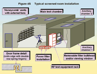
In addition, the shielded room isolates the test and support instrumentation from the RF field. The interconnecting cables leaving the room should be suitably shielded and filtered themselves. A removable bulkhead panel is often provided which can carry interchangeable RF connectors and filtered power and signal connectors. This is particularly important for a test house whose customers may have many and varied signal and power cable types, each of which must be provided with a suitable filter. As well as for RF immunity tests, a shielded room is useful for other EMC tests as it establishes a good ground reference plane and an electro-magnetically quiet zone. Figure 4S shows the features of a typical shielded chamber installation.
4.7.7 Room resonances
A plain shielded room (known as ‘unlined’) will exhibit field peaks and nulls at various frequencies determined by its dimensions. The larger the room, the lower the resonant frequencies. This phenomenon is exactly the same as that which causes problems for emissions tests in shielded rooms. For a room of 3 x 3.5 x 6m the lowest resonant frequency works out to around 50MHz.
To damp these resonances the room is lined with absorber material, typically carbon loaded foam shaped into pyramidal sections, which reduces wall reflections. The room is then said to be “anechoic” if all walls and floor are lined, as is necessary for a compliant immunity test, or “semi-anechoic” if the floor is left reflective. Such material is expensive - a fully-lined room will be more than double the cost of an unlined one.
An alternative to pyramidal absorbers is to line the walls with ferrite tiles or ferrite grid absorbers. These materials are now widely available and can claim extremely good results in damping room resonances, but the ferrites are also expensive and heavy and bring their own problems in fixing and mechanical support. A compromise increasingly in use in modern test facilities is to use ferrites for lower frequency response combined with small pyramidal absorbers to extend the high frequency response to over 1GHz.
4.7.8 Field uniformity
At the higher frequencies the standing waves due to chamber resonance can result in significant variation in the field strength over quite a small volume, certainly smaller than is occupied by the EUT. As a practical measure of the effectiveness of anechoic lining, and to calibrate the field strength that will be used in the actual test, EN 61000-4-3 specifies a measurement of the field uniformity to be made at 16 points over a grid covering a plane area. The measurements are made in the absence of the EUT and the grid corresponds to the position of the front face of the EUT. The field strength at 75% (i.e. 12) of the measurement points must be within the tolerance –0dB/+6dB to be acceptable, though a tolerance of greater than +6dB is allowed provided it is stated in the test report.
The tolerance is quoted in this asymmetrical way to ensure that the applied field strength is never less than the stated level, but it does imply that over- testing by up to a factor of two is possible. Figure 4T gives the geometry for the recommended field uniformity criterion. For smaller EUTs, a smaller uniform area, for instance 3 x 3 points giving a 1m square, is acceptable.
4.7.9 Ancillary equipment
You will need a range of support equipment in addition to the RF test equipment: some form of communication will be needed between the inside of the shielded room and the outside world, to monitor the EUT’s performance without affecting or being affected by the test. This could take the form of RFI-proof CCTV equipment, intercoms or fibre optic data communication links.
4.7.10 Test methods
The major concern of standardised immunity test methods is to ensure repeatability of measurements. The immunity test is complicated by not having a defined threshold which indicates pass or failure. Instead, a (hopefully) well defined level of interference is applied to the EUT and its response is noted. The test procedure concentrates on ensuring that the applied level is as consistent as possible and that the means of application is also consistent.
4.7.11 Preliminary checking
You will need to carry out some preliminary tests to find the most susceptible configuration and operating mode of the EUT. If it is expected to pass the compliance test with a comfortable margin, you may need to apply considerably greater field strengths in order to deliberately induce a malfunction. Hopefully (from the point of view of the test), with the initially defined set-up and operation there will be some frequency and level at which the operation is corrupted.
Once a sensitive point has been found, you can vary the orientation, cable layout, grounding regime and antenna polarisation to find the lowest level which induces a malfunction at that frequency. Similarly, the operating mode can be changed to find the most sensitive mode. It is reasonable to write special test software to continuously exercise the most sensitive mode, if this is not part of the normal continuous operation of the instrument.
4.7.12 Compliance tests
Once the sensitive configuration has been established it should be carefully defined and rigorously maintained throughout the compliance test. Changes in configuration halfway through will invalidate the testing. Equipment should always be tested in conditions that are as close as possible to a typical installation – that is with wiring and cabling as per normal practice, and with hatches and covers in place.
As shown by Figure 4M, the default cable length exposed to the test field is 1m, with excess cable length filtered by a clip-on ferrite and then run close to the metal floor (or walls) of the anechoic chamber. But if the wiring practice is specified, then the specified cabling set-up should be used instead. For example, the length of process control I/O cables is generally unspecified so these are only exposed by 1m. But where (for example) a printer is being tested, if its manufacturer specifies a 2m length of printer cable from the computer, and the computer is in the test environment too, then both printer and computer are set up on the wooden table in the chamber with the specified 2m printer cable between them. If the computer is outside the anechoic chamber and the printer cable has to be extended to reach a bulkhead connector in the chamber wall, then the default 1m exposed length applies.
If the EUT is floor-standing (such as a rack or cabinet) it will be placed on but insulated from the floor, otherwise it should be on a wooden table. The antenna will normally be placed at least 1m from it, at a greater distance if possible consistent with generating an adequate field strength; the preferred distance is 3m. Too close a distance affects the uniformity of the generated field and also, because of mutual coupling between antenna and EUT, invalidates the basis on which the substitution method is used.
The parameters which have been chosen to represent the operation of the EUT must be continuously monitored throughout the sweep, preferably by linking them to an automatic data capture and analysis system – although the test engineer’s eyeballs still remain one of the most common monitoring instruments.
For most types of electronic equipment, a total of eight sweeps are needed – one in each polarisation of the antenna, with each of the four sides of the EUT facing the antenna. If the equipment can be used in any plane, such as a portable handset for example, then you should also test the two other orientations, that is with the top and bottom facing the antenna, making twelve sweeps in all.
4.7.13 Sweep rate and step size
The sweep rate is critical to the test time, and hence the cost of the test, but also it affects the performance of the EUT. According to the standards, the signal generator should either be manually or automatically swept across the output range at 1.5 · 10–3 decades per second or slower, depending on the speed of response of the EUT, or it can be automatically stepped at this rate in steps of typically 1% – that is, each test frequency is 1.01 times the previous one, so that the steps are logarithmic.
The dwell time for stepped application should be at least enough to allow time for the EUT to respond; slow responses translate directly to a longer test time. As an example, to cover the range 80–1000MHz with a step size of 1% and a dwell time of 3s theoretically takes 12.7 minutes (although in practice the control software imposes an overhead and they can take as long as 30 minutes).
For many systems there may be little sensitivity to sweep rate since demodulation of applied RF tends to have a fairly broad bandwidth; usually, responses are caused by structural or coupling resonances which are low-Q and therefore several MHz wide. On the other hand, some frequency sensitive functions in the EUT may have a very narrow detection bandwidth so that responses are only noted at specific frequencies. If the sweep rate through these frequencies is too fast (or the step spacing is too great) then a response may be missed. Such narrowband susceptibility may be 25–30dB worse than the broadband response. Therefore some knowledge of the EUT’s internal functions is essential, or considerably more complex test procedures are needed.
4.8 References
[1]“EMC Testing Part 1 – Radiated Emissions” Keith Armstrong and Tim Williams, EMC Compliance Journal February 2001, pages 27-39. (Also includes Part 0.) Available on-line at http://www.compliance-club.com/ (using the site’s Archive Search facility). [2] “Between design and manufacture” Tom Toth and Mark Exley, IEE ‘Manufacturing Engineer’ Journal June 2000, pages 102 – 104. [3]“EMC for Systems and Installations” Tim Williams and Keith Armstrong, Newnes, January 2000, ISBN 0-7506-4167-3 (available from RS and Farnell). [4] “EMC-related Functional Safety”, Keith Armstrong, ITEM UPDATE 2001. [5] “IEE Guide to EMC and Functional Safety”, IEE September 2000, free download from www.iee.org.uk/PAB/EMC/core.htm as a ‘Core’ document and nine ‘Industry Annexes. [6] “EMC-related functional safety of electronically controlled equipment”, Keith Armstrong, Compliance Engineering’s 2001 Annual Reference Guide, pages 40-50. [7] “New guidance on EMC-related functional safety”, Keith Armstrong, 2001 IEEE EMC International Symposium, Montreal, August 13-17 2001 (session D3-P3, 15th August). [8] IEC 61508-2 “Functional safety of electrical/electronic/programmable electronic safety-related systems Part 2: Requirements for electrical/electronic/programmable electronic safety-related systems” [9] IEC/TS 61000-1-2:2001 “Electromagnetic Compatibility (EMC) – Part1-2: General – Methodology for the achievement of the functional safety of electrical and electronic equipment with regard to electromagnetic phenomena”. [10]“Build Your Test Site Right. Part II” Jon D. Curtis, International Product Compliance (sorry, no date and the magazine has now ceased publication). An earlier version appeared in Conformity October 1997, p. 5, and can be downloaded from http://www.conformity.com/. [11]“Design techniques for EMC – Part 1” Keith Armstrong, UK EMC Journal February 1999 pages 8-22, available on-line at http://www.compliance-club.com/ (using the site’s Archive Search facility). [12]“Chamber Exit Filters for Radiated EMC Testing” Richard Marshall, EMC2000 Conference, York 10/11 July 2000, http://www.yes.co.uk/. Information on these filters also at: http://www.design-emc.co.uk/. [13]“Desk-top Immunity Testing and Diagnostics” Richard Marshall, IEE Colloquium on ‘In-House EMC Measurements and Diagnostics’, Savoy Place London 14th November 2000, IEE Reference: 00/092 (sales@iee.org.uk) [14]“EMC Testing Part 3 – Fast Transient Burst, Surge, Electrostatic Discharge” Keith Armstrong and Tim Williams, EMC Compliance Journal June 2001, pages 19-29. Available on-line at http://www.compliance-club.com/ (using the site’s Archive Search facility). [15]“Achieving High Field Strength at High Frequency in a EC/95/54 150mm Stripline”, Martin O’Hara, EMC York 2000 Conference Proceedings, York EMC Services Ltd (http://www.yes.co.uk/). [16]“Not shaken, not stirred. New reverberation chamber approach” James Page, Approval, Nov/Dec 1997, pages 26-27 [17]“Generating an EMC Test Field Using a Vibrating Intrinsic Reverberation Chamber” Frank B.J. Leferink and Wim C. van Etten, IEEE EMC Society Newsletter, Spring 2001, pages 19-25
Eur
Ing Keith Armstrong C.Eng MIEE MIEEE Email: keith.armstrong@cherryclough.com
Tim
Williams C.Eng MIEE Email: elmactimw@cix.compulink.co.uk
|