EMC Testing
Part 6 – Low-frequency magnetic fields (emissions and immunity);mains dips, dropouts, interruptions, sags, brownouts and swells
By Eur Ing Keith Armstrong C.Eng MIEE MIEEE, Partner, Cherry Clough Consultants, Associate of EMC-UK
Tim Williams C.Eng MIEE, Director, Elmac Services, Associate of EMC-UK
This is the sixth in a series of seven bi-monthly articles on ‘do-it-yourself’ electromagnetic compatibility (EMC) testing techniques for apparatus covered by the EMC Directive (EMCD). This series covers the whole range of test methods – from simple tests for development and fault-finding purposes, through lowest-cost EMC checks; ‘pre-compliance’ testing with various degrees of accuracy; on-site testing for large systems and installations; to full-specification compliance testing capable of meeting the requirements of national test accreditation bodies. Previous articles are available on-line at www.compliance-club.com, using the site’s Archive Search facility.
What is low-cost to an organisation with 5000 employees could be thought fairly expensive by a company with 50, and might be too expensive for a one-person outfit, but we will cover the complete range of possible costs here so that no-one is left out. It is important to understand, however, that the more you want to save money on EMC testing or reduce the risk of selling non-compliant products, the more EMC skills you will need. Low cost, low risk and low EMC skills do not go together.
This series does not cover management and legal issues (e.g. how much testing should be done to ensure compliance with the EMCD). Neither does it necessarily describe how to actually perform EMC tests in sufficient detail to do them. Much more information is available from the test standards themselves and from the references provided at the end of these articles.
The topics covered in these seven articles are:
1) Radiated emissions
2) Conducted emissions
3) Fast transient burst, surge, electrostatic discharge
4) Radiated immunity
5) Conducted immunity
6) Low frequency magnetic fields emissions and immunity; plus mains dips, dropouts, interruptions, sags, brownouts and swells
7) Harmonics and flicker emissions
Table of contents for this Part
6 Low frequency magnetic fields emissions and immunity; plus mains dips, dropouts, interruptions, sags, brownouts and swells
6.1 50Hz-50kHz magnetic field emissions
6.1.1 Fully-compliant LF magnetic field emissions tests
6.1.2 Low-cost test methods for LF magnetic emissions
6.1.3 On-site testing LF magnetic emissions
6.1.4 Magnetic fields and the environment
6.2 50Hz magnetic field immunity
6.2.1 Fully compliant 50Hz magnetic field immunity tests
6.2.2 Low-cost testing of 50Hz magnetic field immunity
6.2.3 On-site testing of 50Hz magnetic field immunity
6.3 50Hz pulsed magnetic field immunity
6.4 50Hz-10kHz magnetic field immunity
6.4.1 Fully compliant 50Hz-10kHz magnetic field immunity tests
6.4.2 Low-cost testing for 50Hz-10kHz magnetic field immunity
6.4.3 On-site testing for 50Hz-10kHz magnetic field immunity
6.5 AC mains supply dips, dropouts and interruptions
6.5.1 Full-compliance testing of dips and short interruptions
6.5.2 A home-made dips, dropouts, and interruptions tester
6.5.3 On-site testing of dips and short interruptions
6.6 AC mains supply sags/brownouts and swells
6.6.1 Full compliance voltage variation (sags only) testing
6.6.2 Swell testing
6.6.3 A home-made sags and swell tester
6.6.4 On-site testing of sags and swells
6.7 Full-compliance testing for three-phase equipment
6.8 Correlating alternative test methods
6.9 References
6 Low frequency magnetic fields emissions and immunity; plus mains dips, dropouts, interruptions, sags, brownouts and swells
Part 0 of this series [1] described the various types of EMC tests that could be carried out, including:
· Development testing and diagnostics (to save time and money)
· Pre-compliance testing (to save time and money)
· Full compliance testing
· ‘Troubleshooting’ to quickly identify and fix problems with compliance tests, or with interference in the field
· QA testing (to ensure continuing compliance in volume manufacture)
· Testing of changes and variants (to ensure continuing compliance).
And Part 0 also described how to get the best value when using a third-party test laboratory [1].
This series focuses on testing to the EN standards for typical domestic / commercial / industrial environments. Other kinds of immunity tests may be required for automotive, aerospace, space, rail, marine and military environments. Over the years these, and other industries, have often developed their own immunity test standards based on their own particular kinds of disturbances, usually for reliability reasons.
See Part 4 of this series [2] for more detail on the following important issues for immunity testing:
· Saving costs by early EMC testing (section 4.1).
· Immunity testing for reliability and functional safety (section 4.2).
The basic EN test methods described here are identical to the basic IEC test methods (e.g. EN 61000-4-8 = IEC 61000-4-8), so this article may also be of use where non-EU EMC requirements apply.
Safety Note: Some of the tests described in this Part involve electrical hazards, particularly those associated with the mains supply, and all appropriate safety precautions must be taken. If you have any doubts about the exact safety precautions you should be taking, ask acompetent person. EN 61010-1:2001 is often the most relevant safety standard in test and measurement situations.
You may even need to go outside your own organisation to find a suitably competent person – if so a local Health and Safety at Work inspector or LVD Notified Body should be able to recommend someone. Health and Safety inspectors can be found in your local telephone directory or directory enquiries, while a list of LVD Notified Bodies and their contact details can be found at the LVD’s homepage:
http://europa.eu.int/comm/enterprise/electr_equipment/lv/index.htm.
6.1 50Hz-50kHz magnetic field emissions
There are no standards in the EN 61000-4-x series covering the measurement of magnetic field emissions under 150kHz, and most harmonised EMC emissions standards don’t include any requirements to measure such magnetic fields. However, LF magnetic field emissions tests might be a useful (or even necessary) part of some Technical Construction Files or in design/development or troubleshooting.
When one item of equipment is in close proximity to another, LF magnetic fields can cause interference. This is especially a problem for CRT image ‘wobble’, but also for baseband circuits such as instrumentation, video and audio, whose circuits and cables can couple with the magnetic fields and suffer significant amounts of crosstalk in some situations.
EN 55103-1 [3] – the so-called ‘PAVI’ standard (short for professional audio, video, and lighting industry) – does include an emission test for LF magnetic fields from 50Hz to 50kHz. Professional equipment such as this is often racked or stacked very close to other equipment and magnetic field coupling can be a real concern.
The companion immunity standard to EN 55103-1 is EN 55103-2 [5] and this includes a test for immunity to LF magnetic fields from 50Hz to 10kHz (see below). Meeting the magnetic field requirements of this pair of standards will help ensure freedom from LF magnetic field crosstalk for items of equipment that will be located close to each other.
The magnetic field test method in [3] is based on the USA’s MIL-STD-462D method RE101, which covers 30Hz to 100kHz. This is similar, if not identical, to the UK’s DEF STAN 59-41 Method DRE02 which covers 20Hz to 50kHz.
6.1.1 Fully-compliant LF magnetic field emissions tests
Because there is no basic measurement method standard in the EN 61000-4-x series to call upon for these LF field tests, [3] describes the test method to be used in detail in its Annex A, which only has two pages. The test is very easy to perform and does not require a special environment, such as a shielded room.
Figure 6A shows the construction details for the loop sensor to be used for the tests. The output from the loop sensor is connected to an audio frequency spectrum analyser with an input impedance greater than 10kW and a resolution bandwidth of 10Hz ±20% and measures the voltage V (rms or quasi-peak). The measured field (H) in Amps/metre is given by the conversion factor (transducer factor) H = 253V/f (when V is in millivolts and f is in Hz).
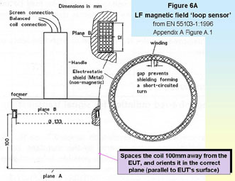
Calibration of the loop sensor is not necessary when it is constructed according to Figure 6A and the above conversion factor is used.
Prior to the test the test environment is scanned with the loop sensor to check that the ambient fields are less than one-quarter of the limits to be measured to, with the equipment under test (EUT) switched off. This is the only requirement for the test environment – although it is a sensible precaution to ensure that any metal objects are at least three times the test distance away from the EUT. Large steel objects should ideally be five times the test distance away. If the local magnetic fields are too high, move the test location somewhere ‘quieter’ (see 6.1.4 below).
During the test the EUT is operated in its normal way with its normal signals, set up so as to cause the worst magnetic emissions. For example, an audio power amplifier would be operated at full output power into its lowest-rated output impedance to maximise its output and power supply currents. Where signals can range over a band of frequencies standard testing waveforms should be used – [3] specifies ‘pink’ noise for audio equipment and 100.0.750.0 colour bars for video equipment.
An EUT with several operating modes should be operated and tested in each mode if it is not clear from a technical analysis which will cause the worst emissions.
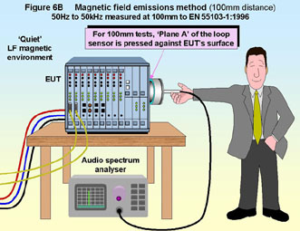
The loop sensor is scanned over the surface of the EUT with a separation distance of 100mm for equipment intended for rack-mounting, or at 1 metre distance for equipment not intended for rack-mounting. The sensor is scanned over the top, bottom, and all sides of the EUT at the specified distance, with the plane of the sensor’s coil parallel to the surface as shown by Figure 6B.
The loop sensor should be held at each test location for at least one sweep of the spectrum analyser. Where emissions could vary (for instance for an EUT that goes through a sequence of operations or states) many sweeps should be taken over at least one complete cycle of operation, preferably several, using the peak-hold mode of the analyser if one exists, so that the maximum readings are identified across the whole frequency range.
Larger diameter coils can be used for the 1 metre tests and will be more sensitive than the loop sensor of Figure 6A. Annex A of [3] gives a formula that can be used to determine the conversion factors for other types of coil.
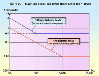
The limits for magnetic field emissions are given in the main body of [3]. They depend upon the intended operational environment of the EUT and the measurement distance, as shown by Figure 6C. The test method states that rms or quasi-peak detectors can be used, but the limits don’t state which detector they are for. Since a quasi-peak detector will measure at least as high as the rms, but never less than it, it is probably best to use quasi-peak.
6.1.2 Low-cost test methods for LF magnetic emissions
It is so easy and cheap to make your own loop sensor fully according to [3] (see Figure 6A) that there is no need to describe a lower-cost probe. It is also easy and cheap to follow the test method in its Annex A in full.
The only real cost issue is the audio-frequency spectrum analyser, especially if it has a quasi-peak detector. In the audio frequency range it is relatively easy to design and construct band-pass filters with known gain in the passband and known filter bandwidths and such a filter could be used in place of a spectrum analyser. Circuits and design equations for suitable band-pass filters are not given here but will be found in most filter design textbooks.
With an oscilloscope or voltmeter (accurate over the frequency range and preferably true-rms) and a manually-tuned band-pass filter a number of frequencies would be measured one at a time and a graph plotted, a fairly time-consuming process given that the frequency range is three decades. It is possible to design voltage-tuned band-pass filters and lock them to the X-axis sweep voltage of the oscilloscope to generate an amplitude/frequency display of the measured voltage – in fact a simple spectrum analyser – and this would make much faster measurements.
Beware of choosing too fast a sweep rate. A 10Hz pass-band requires quite a slow rate of change of frequency if it is to give a correct response. There are formulae for this which will be found in most spectrum analyser textbooks or manuals but the fastest sweep rate can be found by simply varying the sweep rate and finding the rate above which a constant amplitude signal measures less.
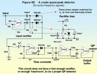
It is also not very difficult to design and assemble a crude quasi-peak detector, following the technical specifications in CISPR16. Accurate quasi-peak detectors are very difficult to design because of their huge overload margins, but the crude design shown in Figure 6D is known to give reasonably accurate results on signals that do not have extreme pulse waveforms.
When testing professional audio, if you don’t have a pink noise generator you could design and make one for the audio band, bearing in mind that pink noise has a spectrum that falls off at 3dB per octave, not the 6dB/octave that a single-pole filter provides. It may be easier to simply hire a suitable pink noise audio signal generator.
Testing audio with sine-wave signal sources instead of pink noise can be done, but can be extremely time consuming because you need to check the whole frequency range for emissions with each test signal frequency. Swept sine-wave sources can help save time. Single-frequency testing can also overtest audio products unless the amplitude is reduced as the frequency increases to approximate a pink noise spectrum. White noise audio signal generators are very easy to make, but will overtest at higher frequencies. (Note that overtesting is not necessarily a bad thing – if the EUT passes without requiring modifications, time and cost may both have been saved.)
6.1.3 On-site testing LF magnetic emissions
Because there are no special test conditions associated with the full test method apart from a quiet enough environment, these tests can easily be employed on-site. See 6.1.4 below for ambient magnetic field issues.
It is also a good idea to move the EUT, if necessary, so it is not close to large metal objects (especially if they are ferromagnetic).
6.1.4 Magnetic fields and the environment
The ambient magnetic field levels at power frequencies in some locations can be surprisingly high. If you can just about see the image on a CRT type VDU ‘wobbling’ or blurring the local 50Hz field is probably close to 1A/m. Most household appliances generate magnetic fields in the range 0.03 to 10A/m, with a maximum of 20A/m, all at a distance of 300mm from their surface. At 1.5m distance their field strengths are typically below 0.1A/m with a maximum of 0.4A/m [4]. A 1kW water pump has been seen to emit 800A/m at 10mm distance, and 3A/m at 400mm, whereas an 18kW motor emitted 6A/m at 200mm.
Under-floor heating has been seen to create 160A/m at floor level and 16A/m at 1m height above floor. 8A/m has been seen at floor level in a multi-storey office and up to 2A/m at desk height, caused by under-floor cables from a large distribution transformer to a switchgear room in a tall building. At ground level under an overhead 400kV transmission line (outside of a building) 32A/m can be found, whereas at ground level above an underground 400kV line the field can be 160A/m.
Although transformers and motors can cause strong fields nearby, the biggest ambient field problems are usually caused by long mains cables or busbars carrying heavy currents, where individual conductors are used for each phase and neutral. Cables that contains all the phases and neutrals associated with a load create much lower fields. Moving farther away from cables will help, but their fields fall off with distance more slowly than for transformers or motors. Where high ambient fields are caused by low-voltage (230/400V) wiring they can usually be avoided by moving a few metres away in the direction perpendicular to the direction of the cable run.
Poorly designed underfloor heating can cause problems for the whole heated area, and underfloor heating for the floor above can be just as bad. Some sites use a combined Protective Earth and Neutral power distribution systems (known as PEN), which can create high levels of 50Hz ambient fields in unpredictable locations all over a site. Some premises have neutral-to-ground faults they didn’t know about which can also create high 50Hz fields over large and unpredictable wide areas.
Remember that the emissions from power cables will depend on the currents in them. Where heavy power cables are nearby, make sure all large machines, heating or lighting loads on the cables are drawing their maximum currents while the environment is being checked. Alternatively, ensure that such heavy current loads are not operated during the tests.
Locations with high-voltage transmission cables nearby (overhead or underground) can have strong magnetic fields over a large area, possibly making it necessary to move some tens of metres perpendicular to the direction of the cables to find a quiet enough environment.
6.2 50Hz magnetic field immunity
Magnetic fields at power-line frequency (50Hz in the EU) are ubiquitous, but high field strengths are uncommon except close to equipment or power cables, or close to heavy power distribution or use (see 6.1.4 for more on magnetic fields in the environment). The basic magnetic field immunity test method commonly called up by the generic and product-family harmonised EMC immunity standards is EN 61000-4-8 [5], which tests at power frequency (50Hz) only.
Most (if not all) of the harmonised standards that call up [5] only apply it to products employing magnetically sensitive components, such as CRTs, electron-multiplier tubes, moving-coil microphones, microphone transformers, hall effect sensors, magnetic recording/playback heads, and the like. Since it is not only magnetically sensitive parts which can suffer interference from 50Hz magnetic fields there are good arguments for testing every new product in this way, at least during development, to check that the expected 50Hz magnetic fields in the environment won’t cause reliability problems in the field (or cause VDUs to fail the Display Screens Directive).
6.2.1 Fully compliant 50Hz magnetic field immunity tests
The test method immerses the EUT in a 50Hz magnetic field created by an induction coil.
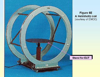
Any suitable induction coil (or arrangement of coils) can be used, as long as it meets the requirements in [5] for field uniformity and calibration. [5] provides useful construction information on three kinds of coil (to cover three different sizes of typical EUT), so that most testers will not need to design their own coils.
Figure 6E shows a proprietary ‘Helmholtz’ coil supplied by EMCO. Helmholtz coils use two induction coils spaced apart to create a more uniform field over a larger volume than is possible with just a single coil. Some proprietary Helmholtz coils have three coil-pairs arranged tri-axially so that the three different field orientations can be tested by just selecting the coil to be driven with switches – no need to move the EUT or the coils.
Induction coils are calibrated by placing a suitable field-strength meter in the geometric centre of the coil and oriented for maximum reading. The induction coil is connected to the test generator using exactly the same set-up as will be used in the actual tests and the generator’s output current to the coil is monitored. [5] calls the ratio of magnetic field to drive current for a coil its ‘coil factor’ (although it would be more commonly recognised as its ‘calibration factor’ or ‘transducer factor’).
The specification in [5] for the test generator is also very simple – it must be able to output sufficient sinusoidal current (with a maximum total distortion of 8%) to drive the induction coil and achieve the required field strength. A suitably rated transformer powered from an AC mains supply with reasonable quality is quite good enough. Figure 6F shows the block diagram of a suitable generator – simply a variable transformer (to set the current and hence the field level) and a high-ratio step-down transformer with an adequate secondary current rating.
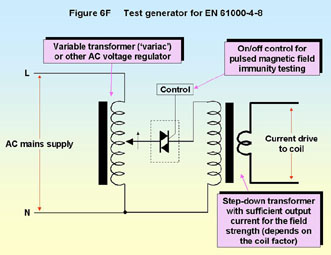
Driving a single-turn induction coil at 100A does not require very much voltage, so the secondary voltage for the step-down transformer might be as low as 3V rms. Induction coils with multiple turns will need proportionally less current for a given field strength, but will need a higher voltage drive.
A variety of field strength test levels are suggested in [5] from 1 to 100A/m, but the generic and product-family harmonised immunity standards which call up [5] usually simply specify levels of 3A/m for domestic, commercial, and light industrial environments, and 30A/m for industrial environments. For some products, especially those used in heavy electrical power environments, or very close to other equipment or power cables, reliability may require testing with field strengths beyond what is required for EMC directive compliance. The method described in 6.1 above could be used to measure the fields in the product’s intended environment.
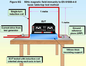
The test set-up for table-top equipment is shown by Figure 6G
Apart from the test generator and induction coil(s) the test instrumentation required is some means of measuring the coil current, which shall have an accuracy of better than ±2%.
As Figure 6G shows, the EUT is placed over a ground reference plane (GRP) which is connected to the local safety earth system. GRPs must be made of a non-magnetic metal, ideally copper or aluminium with a thickness of at least 0.25mm. Other (non-magnetic) metals used for the GRP must be at least 0.65mm thick. The minimum size of the GRP is 1 metre square and it must always extend beyond the EUT on all four sides.
EUTs are placed in the centre of the coil (or coil arrangement) and spaced above the GRP with a 100mm thick insulating support, such as polystyrene or dry wood, and if they have a protective earth terminal this must be connected to the GRP.
The coils must be larger than the EUT on all sides, with a minimum spacing from the EUT of one-third the EUT’s dimension in the plane of the coil. But where the coil is connected to the GRP (as shown in Figure 6G) it need extend beyond the EUT by no more than 100mm along its bottom side. (The coil shown in Figure 6G uses the GRP as one of its sides).
Auxiliary equipment, signal and control cables, power supplies, loads and other test equipment are arranged so that the EUT can be fully exercised during the test and its functional performance monitored with sufficient accuracy to determine a pass or a failure. All the EUT cables are to be exposed to the magnetic field for 1 metre of their length, and any filters required to prevent interference with the auxiliary equipment and/or test gear must have their grounds bonded to the GRP and have 1 metre of cable between them and the EUT.
The fields from the induction coils extend for quite some distance, so it might be necessary to place the auxiliary equipment and/or test equipment some metres away to ensure they are not affected by the field being applied to the EUT. Effective shielding of 50Hz magnetic fields requires substantial thicknesses of metal, so even a double-skinned metal chamber may leak substantially.
The environment conditions for the test are very easy to meet: temperature 15-30OC; relative humidity 25-75%; air pressure 860-1060millibars; and electromagnetic disturbances which are low enough not to influence the test results. The 50Hz magnetic field ambient must be less than one-tenth of the test level. This can be checked with the field strength meter used to calibrate the induction coil, or the loop sensor method in 6.1.1 above.
The generic or product-family harmonised standards will set the test levels to be applied and the performance criteria to be met. Tests are performed with the coil (or coil arrangement) and the EUT arranged so as to test the EUT’s response to magnetic fields in three orthogonal directions, usually front-back, side-side, and top-bottom.
For larger equipment a single coil may be able to ‘illuminate’ a cross-section but a coil arrangement that immerses the EUT in a fairly constant field may be too large and unwieldy. It is acceptable in such cases to use a single coil that is larger than the EUT (as described earlier) to ‘immerse’ a cross-section of the EUT, repeating the test several times with the coil moved along the EUT each time, so that eventually the whole of the EUT (and 1m lengths of its interconnecting and power cables) have been tested. The ‘stepping’ distance for the coil should be no more than 50% of the length of the coil’s shortest side, to ensure overlapping field coverage. To save testing time in such cases, smaller test coils can be used to identify the most susceptible areas of the EUT, and the large coil then placed to immerse just those areas (or volume).
Sensitive equipment not associated with the test should be far enough away not to be interfered with. Safety Note: as a precaution, people fitted with heart pacemakers and similar implanted or body-worn medical devices should not be exposed to the magnetic fields generated by these tests.
An alternative to the mains-powered variable-transformer type of test generator which may be useful where mains supplies are of poor quality, or where programmable field strength levels are required, is to use a signal generator followed by an audio power amplifier. Most proprietary audio amplifiers would find the impedance of a single-turn coil too low to drive without a step-down transformer, but coils with multiple turns could be designed to match the output current rating of a typical audio power amplifier. There is nothing in [5] to limit the technology used for the test generator, as long as it meets the necessary specifications.
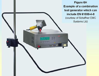
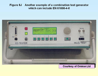
A number of proprietary test instruments exist for full-compliance testing of magnetic field immunity according to [5]. Most (if not all) of these combine several types of immunity tests into one ‘box’ and some are sold with a basic set of test capabilities (usually EN 61000-4-2 and -4-4) to which additional testing ‘modules’ can be added (usually EN 61000-4-5, -4-8, -4-9 and -4-11). The Schaffner ‘Best Plus’ (Figure 6H) is one such test instrument, as is the HILO-TEST unit sold in the UK by Omiran (Figure 6J).
6.2.2 Low-cost testing of 50Hz magnetic field immunity
The test method is so low-cost that it is difficult to find a lower-cost way of performing this test.
If the heavy-gauge conductors and high currents required by single-turn induction coils are a problem, compliant coils can be easily made instead from timber framing and standard gauge wire. 10 turns instead of one will require approximately 1/10th of the drive current, around 3A to create a 30A/m field. The mains current required will be under 1A so a variety of suitable low-cost standard step-down transformers and variable transformers will be available from most distributors. Such a design still creates a compliant test system.
Calibration of the field may be a problem for low-cost, although 50Hz field survey meters are not expensive and can be easily designed and constructed from published articles, e.g. [6] or from the first principles given in most textbooks on alternating current circuits. The loop sensor described in 6.1 above could also be used. Suitable field survey meters can be hired without great expense. Many field survey meters and hobby circuits don’t give the results in A/m, so here are some conversion factors (valid only in air):
· 1 A/m = 4p.10-3 Oersted (Oe) » 12.6 milliOersted
· 1 A/m = 4p.10-7 Tesla (T) » 1.26mT
· 1 A/m = 4p.10-4 Gauss (G) » 1.26mG
6.2.3 On-site testing of 50Hz magnetic field immunity
The test set-up and other requirements in are easy to achieve in most locations. See 6.1.4 above for ambient magnetic field issues.
6.3 50Hz pulsed magnetic field immunity
[5] also describes testing with pulsed magnetic fields up to 1000A/m (or more) for periods of 1 to 3 seconds. This type of disturbance is most likely to be experienced by apparatus exposed to magnetic fields from overhead or underground high-power LV or HV distribution cables, electrical switchyards, electricity substations, or near mains distribution transformers. In these locations strongly pulsed fields can occur during the switching of heavy loads, and during faults in the supply network.
No generic or product-family standards are known to specify pulsed magnetic field testing (at the time of writing) but they may in future (e.g. IEC 61000-6-5 for the immunity of power station and substation equipment, if/when it becomes an EN and harmonised).
The test equipment and methods are specified in [5] and are identical (apart from the generator current output requirement) to those described in 6.2 above.
6.4 50Hz-10kHz magnetic field immunity
This is the companion standard to the LF magnetic field emissions standard described in section 6.2 above [3]. EN 55103-2:1996 [7] is the harmonised ‘PAVI’ immunity standard and it includes tests for magnetic field immunity over 50Hz to 10kHz. The upper frequency may be extended to 50kHz in a later edition to match [3], but there seems no reason why this should not be done already using the same test method. Since there is no EN basic test standard for such tests, the test method is described in full by [7] in its Annex A.
Most other equipment covered by other harmonised immunity standards will have [5] applied. But they may benefit from applying the magnetic field immunity tests in [7] during design/development, troubleshooting, or QA, especially if they are intended to operate in close proximity to other electrical or electronic equipment.
6.4.1 Fully compliant 50Hz-10kHz magnetic field immunity tests
Three types of test are defined, with a specified type of induction coil for each:
· Homogeneous field: one which is substantially uniform in magnitude over a specified volume. This test uses a pair of 1.25m square coils, each of 50 turns of 1.25mm diameter wire, spaced 0.75m apart. Their calibration factor is 48.8A/m per amp of coil current. The magnetic field produced by this arrangement is considered to be uniform enough over a spherical volume with diameter 0.7m centred on the midpoint of the line joining the centres of the two coils. Such paired coils are often called Helmholtz coils and are described by HD 483.1 (see figure 6E for a tri-axial version).
This coil arrangement is used for products which will fit within its 700mm diameter spherical volume and which are not intended for rack mounting or to be used in close proximity to other electrical equipment, or cables carrying significant currents. The EUT is placed with its centroid at the midpoint of the line joining the centres of the two coils and the test carried out. The EUT or the coil assembly is then repositioned to test with the centre-line of the coil orthogonal to the first orientation, and then repositioned again until three orthogonal directions have been tested (usually front-back, side-side, and top-bottom).
Of course, larger Helmholtz coils could be used to test larger products as long as their calibration factor (which [5] calls their ‘coil factor’) is calculated or measured.
· Pseudo homogenous field: one which is substantially uniform in magnitude over a specified region of space. This test uses a 500mm diameter coil having 20 turns of 1.0mm diameter enamelled copper wire in a single layer. It generates 32A/m per amp of coil current at a distance of 100mm from the centre of the coil (perpendicular to the plane of the coil).
This 500mm diameter coil is used as an alternative to Helmholtz coils for larger apparatus which is not intended for rack mounting or to be used in close proximity to other electrical equipment, or cables carrying significant currents. The coil is placed 500mm from the face of the EUT to be tested, with the plane of the coil parallel to the EUT’s surface (similar to Figure 6B) and the EUT is tested. After each test the coil is repositioned to be 100mm from another face of the EUT and the testing repeated until all faces have been tested.
[7] does not say so, but where an EUT has a dimension larger than 1m, the appropriate faces should be tested with the 500mm coil positioned in each 1m by 1m area of that face.
· Inhomogeneous field: one which varies appreciably in both magnitude and direction over a region of space. This test uses a 133mm diameter coil identical to the one used in [3] and sketched in Figure 6A above – except that its ‘EUT spacer’ dimension is 50mm instead of 100mm. This coil generates 138.5A/m per amp of coil current at 50mm from the centre of the coil along a line perpendicular to the plane of the coil.
This coil is used to test equipment that could be rack mounted or could be used in close proximity to other electrical equipment, or cables carrying significant currents. The coil is positioned 50mm from one face of the EUT with the plane of the coil parallel to its surface (similar to Figure 6B) and the test carried out. Each face should be tested with the 133mm coil positioned in each 300mm by 300mm area of that face. It is not clear from the standard which faces should be tested in this way – certainly the top and bottom faces should be tested for rack-mounted or otherwise vertically stacked equipment. Front faces usually don’t need testing but side and rear faces may need to be, depending on the likely installation and use of the product.
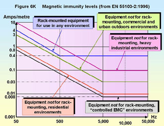
For each of the three types of coil above, and for each position of the coil, the coil is driven by the test generator with enough current to create the specified magnetic field for each test frequency shown – for the five operational environments covered by [7] – in Figure 6K. The test frequency can be continually swept over the whole range 50Hz to 10kHz, or stepped at three spot frequencies per decade. The test continues at each location for long enough for a thorough test given the rate of frequency sweeping/stepping and the mode of operation of the EUT. In addition to the general frequency sweep, spot frequencies known to be used by the EUT are tested (for example, EUTs using EBU time code are tested at 3kHz).
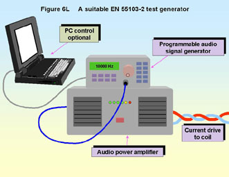
[7] does not specify a suitable test generator, but this would normally be a programmable audio-frequency signal generator and a reasonably powerful audio amplifier. With the coils specified in [7] and at the highest field strength (10A/m at 50Hz) the current required would be less than 500mA. If the load impedance of the coil at 50Hz is too low for an amplifier a step-down transformer could be used to raise the impedance to a more suitable value. It would be a strange audio amplifier that did not like an inductive load, but if stability problems were encountered a parallel resistive load should help. Figure 6L shows a block diagram of a suitable test generator.
As for the immunity tests described in 6.2 above, the EUT should be set-up with all necessary auxiliary equipment; control, signal and power cables; and measuring equipment capable of determining whether the functional performance specifications are met during the test; all arranged so that the auxiliary and measuring equipment are not affected by the magnetic fields of the test. The EUT should be operated using typical real-life signals for its operating mode and which might be expected to be most upset by the tests being carried out. For example, an audio amplifier with a microphone input should be tested with a microphone-level signal and appropriate levels of gain since this is likely to be more susceptible than a line-level signal with lower gain settings.
Again, as in 6.2 above, the ambient magnetic fields should be low enough for the effects of the test to be readily distinguished from the effects due to the ambient. Unlike in 6.2, this requirement extends to all the test frequencies, not just 50Hz. [7] does not specify the ambient field strengths, but at any test frequency they should also be at least 10dB (ideally more than 20dB) below the tested level. Ambient fields can readily be checked using the loop sensor and spectrum analyser method described in 6.1 above.
6.4.2 Low-cost testing for 50Hz-10kHz magnetic field immunity
It is difficult to imagine a lower-cost method of approximating this test than the full-compliance one described by the [7].
However, it might be possible to save testing time (and hence cost) by feeding the power amplifier with frequency-shaped noise instead of a swept sine wave – the amplitude and frequency shaping of the signal would best be designed to create the approximately correct amplitude versus frequency required by [7]. The power rating of the audio amplifier would probably need to be much larger, though, and it would therefore cost more.
6.4.3 On-site testing for 50Hz-10kHz magnetic field immunity
Exactly the same comments apply as in 6.2.3 above.
6.5 AC mains supply dips, dropouts and interruptions
According to some experts, the effects of poor AC supply quality on electronic equipment is one of the most significant causes of downtime and financial loss world-wide. Dips, sags, brownouts, swells, voltage variations, dropouts and interruptions are the main causes of poor supply quality. (In some areas waveform distortion is also becoming an important immunity issue, but that is not covered in this series.)
EN 61000-4-11 [8] is the basic test standard for dips, sags, brownouts, swells, voltage variations, dropouts and short interruptions in the AC mains supply called up by the various generic or product-family harmonised EMC standards. When using the Technical Construction File route to conformity with the EMC directive it is possible to use [8] directly.
For EMC directive compliance it is always the generic or product-family standards that set the actual test levels, but they are often a lot less comprehensive than the tests and levels suggested by [8].
An oil exploration platform had a 230V mains supply with a voltage tolerance of ±100% caused by the effects of starting and stopping its huge drilling motor on its diesel generator. These enormous voltage variations would last for several seconds each. Emergency 230/400V mains generators can have output quality much worse than a typical public mains supply, and much worse than the suggested test limits in [8].
So don’t forget that [8] is only relevant for equipment operated from the public AC mains supply – if your product is likely to be operated on a private mains supply you should find out what it is likely to be exposed to, then design and test accordingly. Standards already exist for the power supplies used in land, sea and air vehicles although they are not harmonised under the EMC directive.
Dips are short-term reductions in supply voltage caused by load switching and fault clearance in the AC supply network. They can also be caused by switching between the mains and alternative supplies in uninterruptible power supplies or emergency power back-up systems. Examples of dips: 30% dip for 10ms, 60% dip for 100ms. Figure 6M shows a 40% dip for 20ms (one mains cycle). A dip of 40% is equivalent to a reduction in supply voltage to 60% of its nominal value.
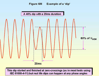
Dips may not occur in isolation - sometimes a fast sequence of dips occurs. Most immunity tests apply dips abruptly, starting and finishing at a zero crossing, but in practice they can have gentler rates of change and start and stop at any point in the mains cycle.
Short interruptions are 80 -100% reductions in supply voltage (dips of 80% or more) lasting for up to 1 minute. The term ‘dropout’ is commonly understood to mean the same thing. Interruptions in the mains supply of more than one minute are simply called ‘interruptions’ and are not covered by [8].
Figure 6N shows a short interruption which is 60ms long (3 mains cycles). Like dips, they are caused by load switching and fault clearance. Also like dips, they can be caused by switching between mains and an alternative supply in uninterruptible power supplies or emergency power back-up systems.

6.5.1 Full-compliance testing of dips and short interruptions
The test set-up is very simple and is shown in Figure 6P.

The characteristics of the generator are specified in section 6.1.1 of [8], with particular requirements for EUT inrush current capability. The inrush current capability should not be limited by the generator: damage due to inrush is often the most severe consequence of a voltage interruption and must be adequately tested. [8] calls for a maximum capability of 500A for 230V mains supplies, but allows it to be less provided that it has been verified, and provided that the EUT inrush is actually less than 70% of the generator’s verified capability. Annex A of the standard gives procedures for measuring both the EUT’s peak inrush current and the generator’s capability, and for full compliance you need to pay attention to these requirements.
A number of commercial products are available for testing to [8], such as those in Figures 6H and 6J.
There are no special requirements for the test environment, except that the electromagnetic environment should allow the correct operation of the EUT and the mains voltage must be monitored and be within 2% of the desired value. The temperature, humidity and air pressure requirements are also very loose (15-35OC, 25-75%, 860-1060mbar), allowing full compliance tests to be done on almost any test bench or floor in most places.
Each dip or interruption test (defined by its dip level and duration, as specified in the relevant generic or product-family harmonised standard) shall be repeated three times with 10 seconds between each, for each representative mode of EUT operation. If 0.5 cycle dips or interruption tests are specified two sets should be done – with 0O and 180O starts.
It is normal for the dips and interruptions tests to start and finish at mains supply voltage zero-crossings, in which case the zero-crossing accuracy of the test should be ±10%. Product-family standards could specify starting and/or stopping at other phase angles, although none that have such requirements are known at the time of writing.
The functions of the EUT must be monitored adequately to identify any degradations during and after each test, and after each group of tests a full functional check shall be performed. The relevant generic or product-family harmonised standard will specify the performance degradation criteria to be applied in each case. In many cases a momentary dimming of displayed images or illumination is permitted during the test.
Where the EUT’s rated supply voltage range does not exceed 20% of its lowest voltage, any voltage within that range can be used for the test. But where the EUT has a wider voltage range two sets of tests are required: one at the lowest rated voltage and one at its highest.
[8] suggests a tougher testing regime than most of the generic or product-family harmonised standards have chosen: dips of 30% and 60% plus short interruptions; each with durations of 0.5, 1, 5, 10, 25 and finally 50 cycles of the supply (i.e. 10, 20, 100, 200, 500, and 1000 milliseconds). [8] also mentions that utilities in Europe have measured dips lasting for up to 3000 cycles (60 seconds) so there may be an argument for testing with even longer dips than suggested in [8].
While it is acceptable for EMC directive compliance reasons to merely test just the dips specified by the relevant harmonised standards, improved product reliability might be achieved by testing over the full range as specified by [8], or for even longer durations – say up to 60 seconds. An assessment of the EUT’s design and components should reveal whether testing beyond the requirements of the harmonised standards could have commercial benefits.
The typical mains supply is nowadays quite likely to be ‘flat-topped’ and not a pure sine wave. This can affect the inrush current and the EUT’s power supply charging voltage – and so can affect the dips and short interruptions test results. Unfortunately, [8] does not specify the waveform purity for the mains supply, so where the EUT’s test supply is derived from the public mains supply we recommend ensuring that the supply meets the requirements of EN 61000-3-3:1995, as follows:
· The test voltage is within ±2% of the nominal voltage.
· The test frequency is 50Hz ±0.5Hz.
· The percentage total harmonic distortion (THD) of the supply voltage shall be less than 3%.
Safety Note: When checking the AC supply waveform, use all necessary safety measures and equipment and leads compliant with the safety standard EN 61010-1 for 230Vrms measurements.
Where the mains supply has a poor waveshape it may be possible to regenerate it with a motor-generator set. Other alternatives include petrol or diesel powered AC generators and continuous double-conversion uninterruptible power supplies. These alternatives can suffer from poor waveshapes and transient noise, inability to supply the EUT inrush current specification, and the internal-combustion powered types can have very poor frequency regulation, so careful selection and dimensioning is required.
There are also certain types of AC mains ‘waveform correctors’ or active power factor correction equipment that can be used to improve a mains supply’s waveform. Any such regeneration or waveform correction equipment may need to be rated for much greater VA or wattage than the EUT so that they can supply the peak EUT inrush current specified by [8].
It is possible to use test generators which synthesise the EUT’s mains supply. These can use an internal sine-wave source and a large power amplifier; or pulse-width-modulation of a DC voltage followed by filtering to leave only the 50Hz. If specified by their manufacturers as being compatible with [8] these should provide the specified EUT supply voltage and inrush currents even where the utility supply has a poor waveform – and their frequency stability should be excellent.
6.5.2 A home-made dips, dropouts, and interruptions tester
It is tempting to do short interruptions testing by manually toggling the EUT’s mains on/off switch OFF and then quickly ON again. In the absence of any more suitable test gear this can sometimes be a useful thing to do. Few low-cost EMC tests cost less than this! However, such testing is very unrepeatable because it suffers from…
· Uncontrolled phase angle at the OFF and ON transitions;
· Sparking at the switch contacts which can cause quite severe bursts of fast transients;
· Hard to control durations for interruptions lasting under 1 second (and probably impossible to get below 100 milliseconds);
· Inability to test for dips – can only test interruptions.
Because high frequencies are not involved in this test it is fairly easy to construct your own supply dips and dropouts tester using a pair of solid-state switches, two variable transformers and a timing generator, as shown by Figure 6Q. Safety Note: All the safety issues associated with mains power must be dealt with correctly! Apply the safety standard IEC (or EN) 61010-1:2001 in full.
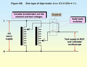
Figure 6Q is copied from [8]. It is easiest to control the switches if they are modular zero-crossing types – they may then be able to be controlled from a standard free-running laboratory pulse generator (driving the switches in antiphase). The block diagram above is not a schematic, so more detailed design is required before commencing construction. Because it uses zero-crossing devices this generator is only capable of switching whole number of half-cycles. This is enough for most (if not all) of the harmonised standards that call up [8] at the moment, but may be limiting. Replacing the ‘solid-state relays’ with IGBTs or power MOSFETs allows the start and stop of the dips and dropouts to be at any phase in the mains waveform. In this case the control circuitry needs to be more sophisticated than a simple free-running pulse generator, so that repeatable switching phase angles can be achieved.
If both power switches could be turned on at the same time (maybe one is slow turning off whilst the other is just turning on) and if the variable transformer is set to a low voltage, there could be a sudden surge of current from the mains supply – so if this is a possibility that hasn’t been prevented by the design a fuse is required, rated to protect the solid-state relays.
To handle the inrush current in a home-made tester it should be enough to make sure that the power switches have single-cycle surge current ratings at least 50 times the EUT’s maximum mains current consumption, and the variable transformer’s continuous power rating is at least five times the maximum VA rating of the EUT.
With the variable transformer set to a given percentage of the supply, the above is a dips tester. With the variable transformer set to zero (or switched out of circuit by not operating the second power switch at all) it is a short interruptions tester.
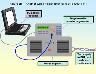
An alternative (see Figure 6R) is to use a programmable waveform generator to drive an audio power amplifier capable of providing the required EUT mains supply voltage and current – including inrush currents. Many standard product audio amplifiers will fall short because of insufficient output voltage or inadequate current, or because they can’t handle the non-linear loads typical of mains power supplies. The voltage requirement may be able to be achieved by ‘bridging’ the outputs of two amplifiers.
6.5.3 On-site testing of dips and short interruptions
The test set-up and other requirements do not require a special test site and so are easy to meet in many locations.
It is often possible to perform full-compliance tests on-site when using appropriate test instrumentation. If there are some out-of-specification issues with the mains supply or other parameters it is often possible to perform pre-compliance tests with reasonable accuracy.
Testing by simply toggling on/off switches should not be considered a repeatable test (see 6.5.2 for reasons) but it may be better than doing nothing at all.
6.6 AC mains supply sags/brownouts and swells
Sags/brownouts and swells are slowly-varying changes in voltage, sometimes over periods of hours. [8] calls these disturbances ‘voltage variations’ and many people are surprised to learn that they are covered by the EMC directive.
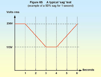
A brownout is another name for a sag, and is the term most often heard in the USA and Canada. Sags can go right down to zero volts. Figure 6S shows the voltage versus time profile for a typical sag test to 50% nominal voltage.
Swells are simply slow increases in voltage which can last up to a few seconds, as opposed to surges and transients which are fast increases in voltage and usually last under 1 millisecond. Swells are sometimes called ‘surges’ by electrical power engineers, but this can be confusing in the EMC world, so this term is not used for this type of disturbance.
Typical mains supplies are specified at ±6% voltage tolerance (sometimes ±10%, as in the UK) and it is not unusual to experience these ranges daily. Safety tests apply ±15% for long periods of time, so voltages of these levels are clearly not impossible. It is often claimed that European mains supplies don’t suffer from the traditional US-style brownout where the voltage falls by a large amount for minutes or even hours – but 60% nominal voltage for an hour or two every weekday used to regularly to occur in parts of Spain in the late 1990s – and 50% nominal for 8 hours was seen in one recent year in a part of the UK.
A significantly lowered supply voltage is a particular problem for all AC motors and some types of DC motor, because they can stall, overheat, and damage their insulation. This can lead to an increased risk of fire, fumes and electric shock, never mind the damage to the equipment. Industrial plant AC motors are usually protected by undervoltage trips which are usually incorporated with other protective functions into motor control circuit breaker devices (MCCBs) – but although the motor is protected the process that it is a part of suffers downtime, and possibly damage to the product as well.
A significantly raised supply voltage (swell) is also a problem. Insulation breakdown and fire hazards should not be a problem for products that meet their respective EN safety standards. But mains surge protection devices such as Metal Oxide Varistors (MOVs) are often designed to start conducting as close to the maximum expected mains voltage as possible, to protect the equipment better. Consequently their leakage currents at voltages much above mains nominal can cause overheating and damage if the swell lasts for more than a few seconds. Maybe [8] assumes that safety testing would discover such problems – we are not so sure of this.
[8] does not suggest doing any swell testing at all.
6.6.1 Full compliance voltage variation (sags only) testing
The test set-up for sags is very simple and shown in Figure 6T.
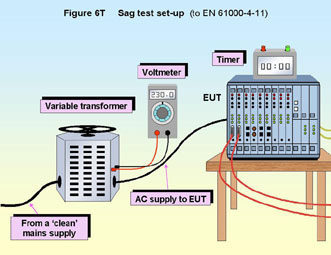
The test conditions are exactly the same as for dips and interruptions testing described in 6.5.1 above.
These tests can easily be done manually by operating a variable transformer under stopwatch control, although many test laboratories will prefer to use a programmable test instrument that complies the generator specification in [8]. The EUT’s mains voltage during the test can be varied smoothly, or it can be varied step-wise providing the steps are no greater than 10% of the nominal mains voltage and occur at the mains waveform zero-crossings.
For each sag test specification (voltage, duration, ramp-down and ramp-up durations) three tests are done, with 10 seconds between each.
The functions of the EUT must be monitored adequately to identify any degradations during and after each test, and after each group of tests a full functional check shall be performed. The relevant generic or product-family harmonised standard will specify the performance degradation criteria to be applied in each case. Dimming of displayed images or illumination may be permitted during the test.
Where the EUT’s rated supply voltage range does not exceed 20% of its lowest voltage, any voltage within that range can be used for the test. But where the EUT has a wider voltage range two sets of tests are required: one at the lowest rated voltage and one at its highest.
[8] suggests two sags tests: 40% and 0% supply voltage each lasting for 1 second with the supply voltage ramped down and then up again over a period of 2 seconds in each case. But most (if not all) generic and product-family harmonised EMC standards don’t specify any testing at all for sags or swells, making it possible to declare conformity to the EMC directive without doing these tests.
However, testing sags and swells according to [8] may be a good way to improve product reliability in the field. In real life, sags can last for minutes or hours at a time so where an assessment of the components and design of a product reveals possible susceptibilities (especially likely where AC or DC motors are concerned) it may be best to test for a longer time than merely 1 second, to ensure reliable operation in the field.
6.6.2 Swell testing
Testing for swells may help improve product reliability in the field. But [8] does not describe testing for voltage variations that are above the nominal mains voltage, so we can’t talk about full-compliance swell testing.
It seems straightforward enough to follow the sag test method in [8] (see 6.6.1) and simply increase the EUT supply voltage instead of decreasing it. This may require a special variable transformer to get the swell range required, or else following a standard variable transformer with a step-up transformer as described by 6.6.3 below.
Most test laboratories would prefer to use a programmable mains synthesising test instrument which met the specifications requirements of [8], but it is likely that these will not be able to provide outputs much higher than nominal mains.
6.6.3 A home-made sags and swell tester
Since full-compliance sag testing can be done with just a variable transformer and manual control, it is hard to suggest a lower-cost method. A large stopwatch with a clearly visible seconds display is a useful aid to maintaining the correct ramp-up, hold, and ramp-down timings. Remember that the dial of the variable transformer may not be very accurate, so check the actual voltages meet the requirements using a reasonably accurate true-rms voltmeter, whilst loaded by the EUT.
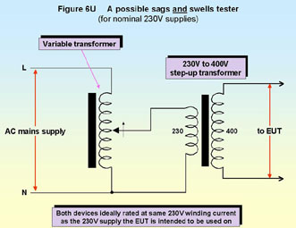
Swell testing could be more difficult though. Most variable transformers only give a limited % increase from their nominal voltage, so it may be necessary to follow the variable transformer with a step-up transformer, such as a standard 230V:400V type as shown by Figure 6U. Because failure modes during swell testing could draw large currents, the variable and step-up transformers used should have continuous 230V currents ratings at least as high as the fuse rating of the 230V supply the EUT is to operate from, or 10 times the EUT’s current rating, whichever is the smaller. Following calibration (when loaded) with a true-rms voltmeter the variable transformer’s dial could be marked-up with stick-on labels as an aid to easy use.
6.6.4 On-site testing of sags and swells
The test set-up and other requirements do not require a special test site and are easy to meet in many locations. It is often possible to perform full-compliance sag and swell tests on-site. If there are some out-of-specification issues with the mains supply or other parameters it is often possible to perform pre-compliance tests with reasonable accuracy and repeatability.
6.7 Full-compliance testing for three-phase equipment
Three-phase equipment is tested for dips, interruptions, and voltage variations using three sets of single-phase test equipment. Phase-by-phase testing is preferred by [8] although some equipment may require simultaneous testing instead (or as well) and this requires common control of the three single-phase test systems. The relevant harmonised standard for the EUT will specify whether phase-by-phase or simultaneous control is required.
Note that when using simultaneous control for dips and interruptions testing, the ±10% specification for the zero-crossing performance can only be met for one phase, so the test generators must be of the type that can switch at any phase angle.
6.8 Correlating alternative test methods
Alternative methods are unlikely to be necessary for most of the tests described in this section, because they are so easy to do in a wide variety of environments.
However, when an alternative immunity test method is used for whatever purpose (e.g. design, development, troubleshooting, QA, variants) repeatability is very important, even though the correlation with the full-compliance test method may not be. So all such tests should follow a written procedure which has been carefully worked out to ensure adequate repeatability. They should also incorporate as many of the specifications of the full compliance tests as are relevant.
When alternative methods are used as part of a QA programme, or to check variants, upgrades, or small modifications, a ‘golden product’ is recommended to act as some sort of a ‘calibration’ for the test equipment and test method. Golden product techniques allow low-cost EMC test gear and faster test methods to be used with much more confidence. Refer to section 1.9 of [1] for a detailed description of how to use the golden product correlation method.
If alternative methods are used to gain sufficient confidence for declaring compliance to the EMCD, the golden product method is very strongly recommended. Without a golden product or some similar basis for correlating with a proper compliance test, the alternative method can only give any confidence at all if gross levels of overtesting are applied, and this can result in very expensive products. Refer to 1.9 in [1].
The closer a test method is to using the proper fully-compliant test transducers and methodology, the more likely it is that a good correlation will be achieved.
6.9 References
[1]“EMC Testing Part 1 – Radiated Emissions” Keith Armstrong and Tim Williams, EMC Compliance Journal February 2001, pages 27-39. (Also includes Part 0.) Available on-line at www.compliance-club.com (using the site’s Archive Search facility).
[2]“EMC Testing Part 4 – Radiated Immunity” Keith Armstrong and Tim Williams, EMC Compliance Journal, August 2001 pages 22-32 and continued in the October 2001 issue. On-line at www.compliance-club.com (using the site’s Archive Search facility).
[3] EN 55103-1:1996 “Electromagnetic Compatibility, Product family standard for audio, video, audio-visual and entertainment lighting control apparatus for professional use, Part 1 – Emission.”
[4]Hewlett-Packard Application Note 1319
[5]EN 61000-4-8:1993 “Electromagnetic Compatibility (EMC), Part 4. Testing and measurement techniques. Section 8. Power frequency magnetic field immunity test. Basic EMC publication.”
[6]“Measuring magnetic fields in your own home”, Alasdair Philips, Electronics World + Wireless World, April 19992, pp 281-283
[7] EN 55103-2:1996 “Electromagnetic Compatibility, Product family standard for audio, video, audio-visual and entertainment lighting control apparatus for professional use, Part 2 – Immunity.”
[8]EN 61000-4-11:1994 “Electromagnetic Compatibility (EMC), Part 4. Testing and measurement techniques. Section 11. Voltage dips, short interruptions and voltage variations immunity tests.”
Eur Ing Keith Armstrong C.Eng MIEE
MIEEE
Partner, Cherry Clough Consultants, www.cherryclough.com,
Associate of EMC-UK
Phone: 01457 871 605, Fax: 01457 820 145,
Email: keith.armstrong@cherryclough.com
Tim Williams C.Eng MIEE
Director, Elmac Services, www.elmac.co.uk,
Associate of EMC-UK
Phone: 01243 533 361, Fax: 01243 790 535,
Email: elmactimw@cix.compulink.co.uk