|
A New Facility for Antenna Calibration By Martin Alexander, National Physical Laboratory, Teddington
Introduction The standard test site for EMC compliance measurements is the 10 m open area test site, according to CISPR publication 161. There is a trend to move radiated RF measurement facilities to indoor shielded rooms for two key reasons: to eliminate ambient RF interference and to enable accurate testing free from inclement weather. In 1993 NPL built Europe’s largest ground plane for the purpose of calibrating EMC antennas, Fig. 1. The area of mild steel plate is 60 m x 30 m, 95% of which is flat to better than ± 6 mm. This has been shown2 to act as a perfect mirror in the frequency range 20 MHz to 500 MHz to an accuracy of better than ± 0.05 dB, extending to 1 GHz to an accuracy of better than ± 0.1 dB. This enables antennas to be calibrated very precisely. Antennas calibrated on this site can be used to develop calibration methods on free-field sites, such as anechoic chambers, and to establish the accuracy of measurements in chambers.
In 2000 a 9 m x 6 m x 6 m shielded room was commissioned, fully lined with ferrite tiles on all 6 interior surfaces. On top of the tiles most of the area was covered with 36” pyramidal foam absorber, the remaining area at the edges being covered with 18” truncated pyramids. NPL became the first UKAS accredited laboratory to perform EMC antenna calibrations in a fully lined chamber. This is an appropriate facility for measuring free-space antenna factor, which is the default parameter for antennas according to clause 3.12 of CISPR 16-1.
NPL has piloted two international inter-comparisons of antenna factor, the first involving 15 laboratories in Europe3 and the second involving national laboratories in USA, Japan and Australia4. NPL had the lowest deviations from the mean results. A third inter-comparison is underway, including China, Korea and Russia.
Calibration methods The original EMC antenna calibration facility5 at NPL was constructed in 1988. 30 m x 10.5 m of wire mesh was laid on marine-grade plywood on a specially levelled area of ground. A motorised mast was purchased and antennas were calibrated according to published methods, most notably ANSI C63.56. A letter of authority was issued by the Radiocommunications Agency to permit testing outside the few narrow frequency bands designated for Test & Development. This allowed the power into the transmit antenna to be increased sufficiently to make measurements at frequencies where ambient interference was preventing the calibration of an antenna. Swept frequency techniques are used to limit the dwell time at any one frequency to milliseconds.
Even so, using the allowed maximum radiated power it was found not possible to calibrate log-periodic dipole array (LPDA) antennas at the recommended distance of 10 m without suffering from interference in the TV broadcast bands. Therefore an extensive programme of work was embarked on to develop an alternative method. The antenna separation was reduced and this necessitated knowing the LPDA phase centres precisely, in order to avoid the increased errors if no corrections were made. The phase centres were measured so that the antenna factor could be calculated for the active dipole elements at each frequency. The phase centre was derived from measurements of the antenna geometry. Polynomials were fitted to the data and splines used when a change in taper on the LPDA occurred. The obtained phase centres were verified by performing the classic phase centre measurement, which is to measure the electrical phase at a fixed frequency as the antenna is rotated in azimuth. This work proved to be most useful in enabling far-field calibrations to be made at short ranges inside anechoic chambers.
The possession of a near-perfect ground plane also made it possible to use fixed antenna height techniques in place of height scanning. This resulted in considerable time saving and worked well in the frequency range 30 MHz to 300 MHz for biconical antennas. Horizontally polarised dipole-like antennas couple strongly to their image in the ground plane. For biconical antennas this can cause the antenna factor to change by 1.8 dB when used at heights above 1 m. However, when vertically polarised, the coupling is weak and this enables quasi-free space antenna factors to be measured.
Figure 1. 60 m x 30 m ground plane, centre axis is 50 m away from surrounding trees
A calculable dipole antenna was developed, whose antenna factor has been demonstrated7 to have an uncertainty of less than ± 0.15 dB in the frequency range 30 MHz to 1 GHz. The antenna is being marketed with software8 incorporating the NEC code so that anyone with the necessary expertise has access to this level of uncertainty, either in free-space or above a high quality ground plane. Recently a miniaturised version of this dipole has been developed to cover the frequency range 1 GHz to 2 GHz, with an uncertainty in antenna factor of less than ± 0.2 dB. This dipole concept was included in the 1999 amendment to CISPR 16-1 as a means of validating antenna ranges being used for antenna calibration.
Accurate calibrations are made possible in fully anechoic rooms (FAR) by the availability of low uncertainty calibrations on the open site of transfer standard antennas, and the possession of the calculable antenna. These antennas can be used to calibrate customers’ antennas by the method of substitution. This method works very well when the transfer standard antenna has similar mechanical dimensions to the customer’s antenna, even in an imperfect field environment. The 9 m FAR has a very good performance, the site attenuation deviating from the theoretical value by less than ± 2 dB at the ends of the band 30 MHz to 1 GHz and within ± 1 dB over most of the central region of this band. Calibrations in the FAR are considerably more efficient than calibrations on the open site ground plane.
Two ferrite-lined chambers have been built at NPL. In the 7 m x 5 m x 5 m chamber, a study9 was made of the effectiveness of ferrite tiles, partially lining and fully lining the walls. A mathematical filter was developed that gave the reflection coefficient of the tiles over a frequency range. This was used in Transmission Line Modelling (TLM) code to calculate the field distribution in the room excited by a source. The calculated normalised site attenuation (NSA) agreed with the measured NSA in most cases to better than ± 1 dB. FARs are expensive to build and a prediction can help prevent costly errors in making the room the wrong size to meet the required NSA criterion.
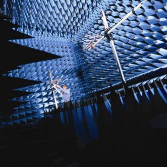
Figure 2. Shielded anechoic chamber, fully lined with ferrite tiles and pyramidal absorber
New methods for calibrating loop antennas and rod antennas have been pioneered. Loop antennas up to 0.6 m diameter are calibrated in a TEM cell that has a spacing of 0.915 m between the plates. Rod antennas are calibrated in a GTEM cell that has a maximum spacing of 1.75 m. Up to 10 kHz the field in the GTEM cell is predicted from the power input to an accuracy of ± 1 dB. From 10 kHz to 30 MHz a calculable rod antenna is substituted for the customer’s antenna. Above 30 MHz the substitution method is performed on the 60 m ground plane. This method of illuminating the antenna with a plane wave is more reliable than the traditional method for calibrating rod antennas, which is a bench measurement in which the monopole element is substituted by a capacitor. The capacitor substitution method can give serious errors above about 20 MHz. Calibration services
NPL is UKAS accredited for the calibration of dipole antennas above a ground plane to an uncertainty of ± 0.35 dB in the frequency range 20 MHz to 500 MHz and generally for EMC wire antennas to uncertainties of ± 0.5 dB in the frequency range 20 MHz to 5 GHz. Hybrid biconical – log antennas can be calibrated to uncertainties of ± 0.7 dB in the frequency range 20 MHz to 2 GHz. Loop and rod antennas are calibrated from 30 Hz to 100 MHz to uncertainties of ± 1 dB and ± 1.5 dB respectively. Conical log spiral antennas are calibrated from 100 MHz to 1 GHz and large horn antennas are calibrated from 200 MHz to 2 GHz.
EMC antennas in the frequency range 1 GHz to 40 GHz are calibrated in a dedicated high frequency anechoic chamber. The gain and radiation patterns of virtually any type of antenna, including arrays, dishes and mobile phones, can be measured. The upper frequency at present is 77 GHz, but the facilities have been designed to enable measurements up to 100 GHz to be made.
Field probes are calibrated in a range of TEM cells and anechoic chambers over the frequency ranges 10 Hz to 2.5 GHz (up to 500 V/m), up to 18 GHz (up to 300 V/m), up to 40 GHz (up to 200 V/m) and up to 45.5 GHz (up to 100 V/m)
A site evaluation service is offered, measuring normalised site attenuation of ground plane test sites and fully anechoic chambers, typically to standards EN50147-2 and prEN50147-3. There is also a service to measure field uniformity to EN61000-4-3. The NSA of ferrite-lined FARs can be computed using TLM.
Since 1990 a lot of effort has been spent enhancing the efficiency of the services, by improving the measurement techniques and automating data acquisition and certificate preparation. This brought calibration prices down for the standard uncertainties and allowed them to remain stable for several years. The calibration prices are very competitive, but for those customers who want lower uncertainties, such as ± 0.5 dB for some services, there is an additional cost. The standard turnaround is 2 weeks, a full set of ANSI calibrations at more than one distance involves several days of measurements. However the majority of calibrations are for free-space antenna factor and with the advent of the new indoor facilities a 1 week turnaround can be offered. The service is continuous throughout the year, but book early to avoid delays on lead times. It is possible to offer faster turnaround times, as little as 1 day for the premium service providing the customer delivers the antenna by the appointed time.
References: 1 CISPR publication 16. Specification for radio disturbance and immunity measuring apparatus and methods, Part 1:1999 Apparatus, Part 2:1996 Methods, Central office of the IEC, 3 rue de Varembé, Geneva, Switzerland.
2 M.J. Alexander and M.J. Salter, “Low measurement uncertainties in the frequency range 30 MHz to 1 GHz using a calculable standard dipole antenna and national reference ground plane”, IEE Proc. Sci. Meas. Technol. Vol. 143, No. 4 July 1996, 221 - 228.
3 M.J. Alexander, “European intercomparison of antenna factors in the frequency range 30 MHz to 1 GHz”, IEE Proc. Sci. Meas. Technol. Vol. 143 , No. 4 July 1996, 229 -240.
4 Alexander, M.J., International comparison CCEM.RF-K7b.f, (GT-RF 92-8): Results of an intercomparison of EMC antenna factors in the frequency range 30 MHz to 1000 MHz - non-resonant dipole antennas, to be published in Metrologia
5 M.J. Salter and M.J. Alexander, “EMC antenna calibration and the design of an open-field site”, Jnl. of Phys. E, Meas. Sci. Technol., 1991, 2, 510-519.
6 American National Standards Institute, ANSI C63.5:1988. Calibration of antennas used for radiated emissions measurements in electromagnetic interference (EMI) control
7 Alexander M J, Salter M J, Loader B G and Knight D A, Broadband calculable dipole reference antennas, IEEE Trans. EMC, Vol. 44, No.1, pp 45-58, February 2002.
8 Salter M J and Baker S, RDS9980: Windows software for broadband calculation of site insertion loss and antenna factor, Schaffner Ltd.
9 L. Dawson, J. Clegg, S.J. Porter, J.F. Dawson, M. Alexander, The use of genetic algorithms to maximise the performance of a partially lined screened room, IEEE Trans. EMC, 2002.
|