|
Equipment Cabling and EMC Testing By R C Marshall, Richard Marshall Limited, UK
Overview This article reviews the rôle of cables during the testing of Electromagnetic Compatibility (EMC) together with the effects of different treatments of a cable at the test chamber boundary. These effects can be understood by considering the cables and Equipment Under Test (EUT) as an antenna system. Comparison with real-life installations suggests ways of improving test relevance and repeatability, and raises the question: Should an EMC test seek to implement the worst case or the typical behaviour?
Hardware methods for setting up measurements according to both philosophies are described.
Background Radio frequency radiation efficiency - in either emission or immunity mode - depends on size in relation to wavelength (where wavelength in metres = 300/frequency in Megahertz). It has long been understood that where the EUT is small in terms of wavelength the cables are the dominant coupling route, and it is for this reason that below 30MHz it is customary to neglect the radiation field in favour of common-mode cable measurements. In a test chamber at higher frequencies we must expect cable effects to remain important since the cables associated with an EUT are rarely shorter than 1 metre, and the miniaturisation of today’s electronics means that most products have their longest dimension no greater than this.
Today’s emission test standards require that cables be positioned to maximise emission. This is an impractical requirement since the worst-case layout is likely to be different at different frequencies, and so it is usually also required that the cable layout be recorded - though to record the position of a cable to a tenth of a wavelength at 1GHz as would be necessary to ensure total repeatability requires a positional accuracy of 30mm which is only rarely achievable.
Standard test methods are either silent or unsatisfactory about how cables should leave the test chamber. For example, CISPR22 suggests that the mains cable exit via a junction box or artificial mains network bonded to the floor. Such an arrangement provides a near-zero common-mode impedance at this point - hereinafter called the “boundary impedance” or “exit impedance“ - much lower than is likely to be encountered in practical use. There is no statement about data or control cables, which is especially problematic for twisted-pair data and communication cables that have no shield that can be bonded to the chamber wall. A metallic tube - a “wave guide below cut-off” is often used but the impedance that this provides will vary widely with frequency because of the resonance of the coaxial stub formed by the cable within the tube.
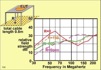
There is increasing interest in the effect of cable boundary impedance on the results of emission and immunity testing. SB Worm¹ has measured the emission from a table-top dummy EUT with a single 0.8 metre cable to the ground-plane of an open-area test site. Some of his data is reproduced here in Figure 1. It may be seen that changing the common-mode impedance at the ground-plane boundary point from zero to infinity results in changes of 10 to 15dB in coupling at frequencies of 30-60MHz and almost as great a change (though in the opposite sense) in the 100 to 180MHz region.
Fig. 1. Field strength as a function of available power for a desk-top EUT (Data from Worm1)
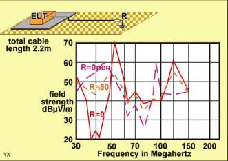
E Ristig² has conducted similar measurements in a chamber using a floor-standing dummy EUT with 2.2 metres of cable running across the floor to the boundary point. He notes 20 to 30dB differences as shown here in Figure 2.
Fig. 2. Field strength as a function of available power for a floor-standing EUT. (Data form Ristig2)
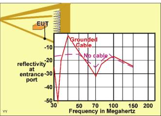
M Böttcher and co-authors³ have made calculations and measurements in a GTEM cell. Extracts from their measurements are redrawn in Figure 3, which shows that the reflectivity of the cell, and hence the coupling efficiency within it, is drastically affected by the presence of a grounded EUT cable.
Fig. 3. Reflectivity of a GTEM cell. (Data from Böttcher et al.3)
These three figures all exhibit strongly-resonant behaviour when the cable is given very either very low or very high resistive impedance at the boundary. This may be understood by considering the EUT and cable(s) together as a transmitting antenna as it is so far as interference emission is concerned.
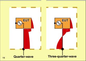
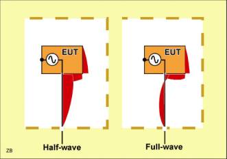
Analysis In Figure 4 the cable, (or more correctly, its ground wire or its shield) is shown connected to the chamber floor to provide a very low common-mode impedance at that point. This “antenna” is excited by a voltage produced within the EUT and developed between the cable connection point and the body of the EUT - perhaps part of the body of a plastic-cased EUT or all of a well-bonded metal EUT. The current distribution along this antenna depends upon its length and the frequency. This distribution is shown in the left hand image of Figure 4 for the lowest-frequency resonance, that is the “quarter-wave” case. The current magnitude is illustrated by the width of the red line away from the cable or the EUT surface. It is a maximum at the low-impedance point at the lower end and falls progressively to the necessary zero at the extremity of the EUT. This antenna functions similarly to a top-loaded quarter-wave as is commonly used for medium-wave broadcasting with the differences that it is much smaller, and power is fed into the antenna near the top rather than at ground level. The 0.8 metres cable to the EUT analysed in figure 1 must have its “effective length” extended by the EUT box to a total of 1.25 metres in view of the strong resonance at 60MHz that may be seen for R=0. Below this frequency emission remains unnaturally enhanced by the low ground impedance.
This cable configuration also resonates at odd multiples of the quarter-wave frequency; The right-hand half of Figure 4 shows the three-quarter wave resonance with an additional point of zero current on the cable. Note that emission from the cable below this zero point is out of phase with that above, as is shown here by the red contour moving to the other side of the cable. This leads to partial cancellation in the direction at right angles to the antenna cable but enhances radiation at high and low angles that may not be detected during testing. Figure 1 does show this reduced horizontal radiation in the region 100 to 180MHz, but the resonance is broad and less than the 180MHz expected from this simple theory because of the effect of the lumped impedances presented by the EUT and the adjacent right-angle bend in the cable.
Fig. 4. Current distribution on an earthed cable and EUT surface
The case of infinite impedance at the boundary may be understood with the aid of Figure 5. Since the current must be zero in an infinite impedance the current distribution must go to zero at the floor as well as at the extremity of the EUT, that is each resonance must correspond to an effective length of one or more half wavelengths. For the configuration plotted in Figure 1 and open circuit termination we would therefore expect the observed maximum at 120MHz.
Fig. 5. Current distribution on an unearthed cable and EUT surface
Implications A real-life installation of electronic equipment such as in Figure 6 will have “untidy” cable connections to the outside world. These are characterised by random - but not usually very tight - coupling to other cables and to conductive and dielectric structural elements and must present an ill-defined common-mode impedance. This will certainly not correspond to either the very high or very low cases that have been analysed above and so the resonances encountered during test are quite unrepresentative of real life.
There are two distinct arguments for manipulating the common-mode exit impedance. The first is to avoid resonance because resonance leads to erratic test results. The second is to match real-life impedance because this affects the average test result, particularly at the low-frequency end of the spectrum. These criteria do not necessarily lead to the same optimum value, but the uncertainties about the choice to meet each criterion are very great and so it is reasonable to seek a single compromise value.
Fig. 6. A real-world IT installation and its cabling
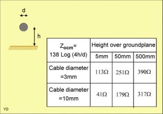
Although 150 ohms has been widely adopted in standards (eg for conducted immunity4 ), there can be no analytically-satisfying rationale for this except to observe that this figure is near to the geometric mean of the characteristic impedance that have been calculated for a variety of typical cable diameters positioned at typical distances from ground and tabulated in Figure 7. Note that in Figure 1 a 150ohm termination was not as effective in removing resonance as was 300ohms - but in this test situation the single EUT cable was well away from other objects.
Fig. 7. Characteristic impedance of a cable above a ground plane
There is really no case for adopting any figure other than 150ohms as being representative of real-life data and telecommunications cabling, and it is practically convenient to be able to make use of existing standardised 150ohm test equipment such as CDNs.
Worst-case or Typical Testing The present-day practice of grounding cables - at least power cables - at the chamber boundary can now be seen as an unrealistic over-test since it results in quarter-wave resonance of the cable at a frequency in the region of 60MHz, and increased interference current flow at this and lower frequencies. It is a worst-case that must have cost manufacturers and their customers dearly over the years - though perhaps it is also a necessary environmental benefit cunningly concealed within the test method. Equally, grounding cables results in under-test at rather higher frequencies, where the worst case would be an open circuit.
To conduct a genuine worst-case test at all frequencies would require switching the boundary impedance between open and short circuit. This is entirely practical using the methods discussed below.
Alternatively one can argue that only a typical situation should be subjected to test - after all, the statistics of typical culprit/victim separation underlies the limits of all EMC standards, so it would be reasonable to include common-mode impedance variations within these statistics. This can be achieved by implementing a 150ohm boundary impedance by a variety of methods as will also be described below.
The world’s Standards bodies need to face up to this choice and clarify their cable boundary requirements. Meanwhile, there is scope for national and industry group decisions and codes of practice.
Testing with Switched Open/Short Circuit Boundary Impedance To recap, emission and immunity testing should be performed under two sets of cable conditions, firstly with very low common-mode impedance where each cable exits from the test chamber, and secondly with very high impedance at this point. This change of exit impedance will have the effect of drastically altering the resonant frequencies of each cable to explore very different resonant conditions, and the worst-case results will then be recorded as the formal test figures. This will lead to the following advantages;
* A measure of automatic worst-case cable layout selection, so reducing the inconsistencies now experienced due to human judgement. This will be particularly important for immunity testing where there is often no way by which the worst layout for susceptibility can be chosen.
* Some of the ambiguities and inconsistencies in existing standards and test practices will be circumvented.
* The existing over-test of power cable emission at frequencies below 100MHz, (due to a low test chamber/OATS exit impedance compared with practical use) is maintained, so preserving historical consistency of test results.
* In a fully anechoic room, where the anechoic walls make it difficult to define a conductive boundary to the test volume, this approach allows the switched connection of cables to each other and to a small reference plate, once again implementing a degree of automatic worst-case cable layout selection.
It should be noted that emission from more than one element can lead to cancellation or addition as the frequency is changed. With two or more cables cancellation can cause very deep nulls over narrow frequency bands, whereas addition results in modest increases over wider frequency ranges. Therefore, whilst it is a convenient use of words to say that the objective of optimising cable emission it to secure the maximum emission or susceptibility, it is actually a more important benefit to avoid the minimum case.
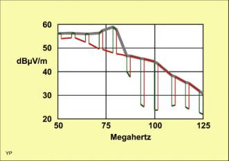
An extra advantage results if the switching between open and short circuit can be accomplished sufficiently quickly for the detector of a measuring receiver to observe both configurations during a single frequency sweep and select the worst case. As an example of this Figure 8 shows measurements of the emission from an EUT with two cables on the OATS5 at the National Physical Laboratory performed on behalf of the DTI NMSPU. The orange curve is the undisturbed emission, and the green is that which resulted when the second cable’s resonance was disturbed by switching in ferrite damping next to the EUT with an opto-coupled fast switch like that to be described below in connection with Figure 13. Note that the “undisturbed” condition gives the greater emission below 80MHz: above this frequency the second cable approaches resonance and partially cancels the emission from the first unless its resonance is damped. The switching steps are more widely spaced in this diagram than they would be in practice. They show how the composite signal reaching the receiver jumps between the values for the two conditions. The broad grey line illustrates how the output of the peak detector following whichever signal is the largest.
Fig. 8. Dynamic selection of worst-case cable emission (Data from Gonzales5)
Whilst for simplicity most of the implementation examples below show a relay contact as switch (indeed, it may be preferred for the higher power level of immunity testing), the use of a semiconductor device with switching times of a few microseconds allows advantage to be taken of the peak or quasi-peak detector in a measuring receiver to select the worst-case during a single frequency sweep. Using the quasi-peak detector according to CISPR16 each switch state needs to be maintained for only 2 milliseconds to enable the measuring receiver to register the strength of the emitted field under those conditions. Combination of this “on” time with a rather longer “off” period gives a spectrum-analyser display very like that of figure 8 in which the two states may be easily distinguished.
Unless frequency scanning is being deliberately slowed to catch infrequent impulsive emissions the two measurement sets may thus be made without any penalty of increased test time.
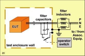
Switched-Impedance Filter Implementation Figure 9 shows a test set up for an EUT together with a switchable exit filter for a three-core unshielded power cable of which one core is grounded. The presence of this ground wire, and the acceptability of decoupling capacitors from the phase and neutral wires to ground, makes it very easy to adapt the usual power filter network for this application.
Fig. 9. Switched boundary filter for a 3-core power cable
In the figure the heavy dashed line represents the conductive test enclosure - or a plate below the EUT in a FAR. The measuring antenna or other field coupling means are omitted for clarity. A single three-core unshielded cable from the EUT is lead through the chamber boundary wall and a series element comprising choke coils in each core provides a high common-mode impedance to radio-frequency signals flowing towards the boundary, so ensuring a current minimum at this point. However, the ground conductor and two filter capacitors are linked so that closure of the switch results in a very low common-mode impedance at radio-frequencies. There will then be a current maximum at the chamber boundary. This will lead to the desired complementary resonance conditions.
It is not necessary for the choke coils to be inductive: Indeed to provide a high impedance over a wide frequency range a substantially resistive choke action such as may be achieved with a lossy ferrite core may be preferred. The coils would be equally satisfactory arranged as multiple windings on a single common-mode choke core.
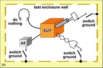
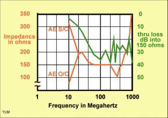
Not all EUT cables actually need to pass through the test boundary. Some, such as mouse or headphone cables, are necessarily short and will be resonant in practical use: these should not be touched. Others are long in practice but may be terminated without loss of test integrity at the chamber boundary by a small item of Associated Equipment (AE) or by differential-mode termination components. Switched common-mode terminations for these may be arranged easily as shown in Figure 10.
Fig. 10. Switched terminations for cables that do not leave the test area
Note that for a coaxial cable such as is shown at the top right of the figure the differential-mode termination resistor is quite separate from the common-mode grounding switch. However for the unshielded twisted pair shown at bottom right the termination resistor must be centre-tapped to provide an appropriate switch connection point.
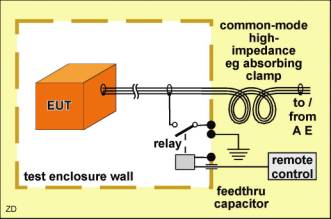
Fig. 11. Switched boundary filter for a 2-core shielded core
Figure 11 shows an example of a switched filter for a coaxial or multi-core shieldedcable. The desired high series impedance is provided by a common-mode choke which may take the form of several ferrite sleeves. Alternatively a length of the cable may be wound into an air-cored choke coil, or the cable may be passed through an “absorbing clamp”. The impedance switch is directly connected to the cable shield and - in this example - utilises the contact of an electromechanical relay whose coil is energised by a remote control. To minimise rf leakage though the chamber wall the relay coil circuit includes a decoupling lead-through capacitor together with a ground return.
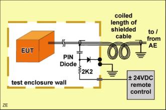
In the case of unshielded cables carrying high-speed data it is not possible to access the cable in common-mode using capacitors as was shown in figure 9 since these would produce unacceptable differential mode loading or impedance discontinuity. In such a situation capacitors may be replaced by the distributed capacitance of a length of shielded cable outside the test enclosure as shown in figure 12. In this arrangement the shielded section tends to act as a resonant coaxial stub whose end nearest the AE is open circuit. To prevent this from reflecting a high impedance in series with the switch it may be desirable to ensure adequate resistive loss in the shielded section by providing a lossy dielectric or by inserting resistors in series with the shield at intermediate points along its length. Alternatively, it may just be made very long. Tests on Cat 5 FTP data cable have shown that the coaxial cable formed with all the 8 conductors in parallel as the inner, and the foil shield as the outer, has a characteristic impedance of about 15 ohms, and also that a 70 metre length has sufficient inherent loss at 30MHz to limit the SWR to about 2.6:1, which limits the maximum impedance that might be seen in series with the switch to a tolerable 40 ohms.
Figure 12 also shows how the switch in this or the previous examples may be implemented by using a semiconductor PIN diode which is biased by a dc potential supplied by the remote control. The 2.2Kilohm resistor prevents the remote control circuit from unduly reducing the impedance of the diode switch when this is “open”, and defines the diode current when it is closed. If the output of the remote control is held negative by 24 volts with respect to ground then the PIN diode is reverse biased and presents an impedance of some 0.3pF so that the “switch” is effectively open. If on the other hand the output of remote control is held positive with respect to ground then the PIN diode conducts and assumes a resistance of less than 10 ohms so that the “switch” is effectively closed. PIN diodes are doped to control their switching time so that they do not introduce significant harmonics or inter-modulation effects at radio frequencies. Such a diode switch has the advantage of very fast operation but the disadvantage of limited voltage- and current-handling capability. It is therefore preferred for emission testing, whereas a relay contact may be better for immunity testing at high field strengths.
Fig. 12. Switched boundary filter for a 2-core unshielded cable using external shielded cable and a PIN diode switch
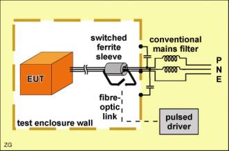
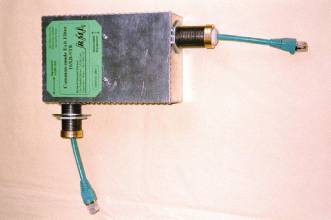
Figure 13 illustrates another approach; a split-ferrite common-mode impedance is assembled onto an EUT cable adjacent to a conventional low-impedance boundary filter. Normally this will result in a high common-mode exit impedance, but the ferrite is also equipped with a secondary winding that may be short-circuited to nullify the added impedance and restore the low-impedance condition. Since a control cable within the test chamber might disturb the rf field the switch is controlled by a fibre-optic link.
Fig. 13. Isolated cable impedance switch
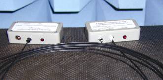
An early example of the hardware needed to do this is shown in Figure 14. Each grey box contains a battery and “On “ indicator LED. The left-hand box has a hole through which the EUT cable passes to the ferrite sleeve inside: The right-hand box carries the on/off/pulsed switch for both units which are linked by the fibre shown coiled in the foreground. This technique has the advantage that it may also be applied at the equipment end of the cable5, or to a cable that links two separate assemblies of a single EUT.
Fig. 14. A prototype isolated cable impedance switch
In the case of an EUT with two or more connecting cables leaving the test enclosure both positions of the impedance control switch associated with each cable must be explored in several, but not necessarily all, possible combinations so as to get sufficiently near the worst-case electromagnetic coupling without excessive test time. Intuitively it seems that since the low-impedance state gives more emission at low frequencies and enables current to flow in loops formed by two cables, the minimum test pattern should be to set one cable at a time into the high-impedance state.
Realising a 150 ohm Boundary Impedance As explained earlier, implementing a boundary impedance of 150 ohms provides a more realistic test environment. It also damps cable resonances which may otherwise mask or accentuate critical emission or immunity problems. Such resonances are also critically dependent on cable length and layout and so contribute significantly to the measurement uncertainty.
Previous methods of taking cables through the walls of EMC test chambers have used filters designed for other purposes. For example recent work communicated within CISPR has discussed the use of the absorbing clamp as a device to reduce cable resonance. This has been shown to be helpful but far from perfect: The clamp has an excessively high common-mode impedance (recorded by Worm¹ as in excess of 1,000ohms at 30MHz) and so does not damp resonance optimally. The absorbing clamp also exhibits insufficient attenuation, which is manifest from the variation of its EUT-side input impedance as the AE-side load impedance varies. Furthermore it is bulky, and unlikely to be available off-the-shelf in sufficient numbers to cover the requirements for testing multi-cable EUTs.
Worm¹ concludes that Coupler-Decoupler Networks to EN61000-4-6 4 are technically suitable for use as boundary filters in radiated field testing. Some manufacturers6 of these offer an extended frequency range that makes them particularly suitable for this application. However they are intrusive to the cable, whilst the absorbing clamp is not.
As discussed above for switched impedances, cables that do not have to pass through the boundary may be dealt with very easily by terminations similar to those in Figure 10 but with a 150 ohm resistor in place of the switch contact.
For other cables the switched filters shown in Figures 11 and 12 may be adapted in the same way to provide a constant 150 ohms common-mode impedance.
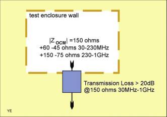
However, the most desirable solution is a boundary filter which combines 150 ohms common-mode impedance with the convenience of clamp-type construction so that the EUT cable need not be cut or shortened. This has been achieved by the combination of both series and shunt elements7. This design was aimed at the target specification in Figure 15: namely an exit impedance in accordance with EN61000-4-6 over the frequency range 30 to 230MHz, and extended to +150 -75 ohms from 230 to 1000MHz, together with a through-boundary attenuation of 20dB over the range 30-1000MHz when measured between 150 ohm terminations. Whilst we have followed the conventions of the standard it has to be said that the specification of the modulus of the termination resistance is not the best way to specify impedance in this context: It would be better to specify the SWR, perhaps as <1.5 below 230MHz and <2 above.
Fig. 15. Exit filter target specification
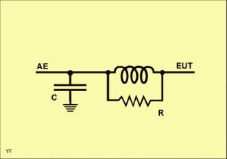
Non-Intrusive Boundary Filters It is evident from the above discussion that the high impedance and limited attenuation of the absorbing clamp - which was designed for a quite different application - arise from the lack of any intentional shunt element. Since it is desirable that an exit filter be non-intrusive to the cable, such a shunt element must involve a capacitive coupling to the outside of the cable. This may be achieved by bringing earthed material into close contact with the cable outer. An appreciable length of cable needs to be contacted to provide a useful capacitance, but this treatment will then form a transmission line whose resonance may disturb the filter characteristics if it falls within the operating frequency range. Accordingly we have made multi-section filters comprising several sections each using a ferrite sleeve as series element working with a capacitive section whose length is optimised to cover just part of the frequency range. The common-mode equivalent circuit of a single section is shown in Figure 16.
Fig. 16. Common-mode equivalent circuit of exit filter section
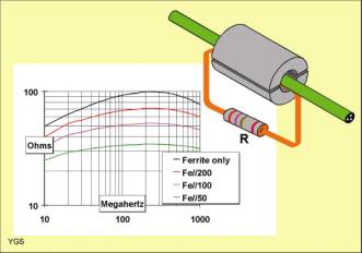
Each series element comprises a ferrite sleeve whose impedance is modified by adding a shunt resistor coupled by a secondary winding as shown in Figure 17. This figure also shows graphically the effect that the shunt has in achieving the necessary precision of impedance over a wide range of frequencies. It should be noted that special precautions must be made to minimise the leakage inductance of this secondary winding. Combining several of these series elements with wire-mesh capacitive shunt elements can produce compact exit filters for specific cable types, such as that shown in Figure 18 for 4-pair LAN and telecommunications cables6. The threaded conduit ends of this filter allow mounting directly on the inside or outside of a test chamber wall.
Fig. 17. Modification of ferrite sleeve impedance using an inductively-coupled resistor
Fig. 18. A practical 150 ohm exit filter for data and telecommunications cables
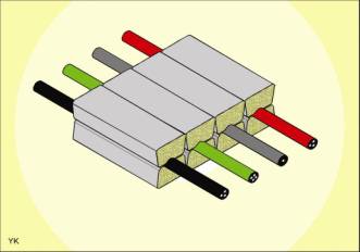
For general-purpose use a split construction like that of the absorbing clamp is very desirable. Split ferrite cores are commonplace, but to complement these split shunt elements are required. It has proved possible to use conductive fabric supported on soft plastic foam to form a clip-around shunt capacitor of some 300pF per metre. This results in a practical, but relatively bulky assembly. However its bulk may be concealed in a cable duct which also allows the construction of economical multiple cable assemblies to support the testing of EUTs with several cables to the outside world. Figure 19 shows how a 4-cable shunt capacitor may be arranged for easy assembly into a 100mm wide duct. This particular width is chosen for compatibility with the standard 100mm ferrite tile.
Fig. 19. Shunt-capacitive loading of cables in a duct
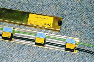
A complete 2 cable, 5 section clamp filter using similar construction6 is shown in Figure 20, where it may be seen to carry a 3 core 1.5mm² mains cable and a Cat. 5 data cable in an arrangement that avoids rewiring of connectors yet allows all surplus cable to be outside the test chamber, eliminating the uncertainty often introduced by cable bundling. The common-mode impedance and attenuation of this actual filter is plotted in Figure 21 and can be seen to closely match the design goal. The differential mode attenuation is of course just that of the piece of cable passing through the assembly.
Fig. 20. A practical 150 ohm exit filter for general-purpose use
Fig. 21. Common-mode characteristics of the general-purpose exit filter
A particularly straightforward clamp filter may be constructed for power and shielded cables that may be grounded at the exit point to achieve near-zero impedance there. This impedance may then be raised to the desired value by substituting one or two resistively-loaded ferrite sleeves into the configuration of figure 13.
Conclusion The management of cable impedance offers improvement to the reproducibility and real-world relevance of almost all radiated-field EMC test methods. The test hardware needed is simple, and there is little or no impact on test time. Whilst there is a need for the clarification and improvement of standards in this area there is also scope for immediate implementation of some of the principles and practices described.
The author will be pleased to discuss these matters. Contact richard.marshall@iee.org
Acknowledgements Martin Alexander of the National Physical Laboratory has introduced me to others working in this field and provided long-term encouragement and support.
Some of the hardware arrangements described in this paper are the intellectual property of Richard Marshall Limited. Commercial licenses are readily available.
References 1) S B Worm, On the relation between radiated and conducted RF emission tests, Philips Research, 13th International Zurich Symposium & Technical Exhibition on EMC, February 16-18, 1999, pp515-520. 2) “Placement of ferrites on cables exiting the EUT (Floor standing and Table-top)”, E Ristig, Private communication from the author referenced as CISPR/A/WG2 project FAR/Convenor 5 (March 1999) 3) “Numerical Simulation of a GTEM Cell” , M Böttcher, P Noack, & F Reichert, 12th International Symposium on EMC, Zurich, 1997, pp333-338 4) “Electromagnetic Compatibility (EMC) Part 4: Testing and measurement techniques. Section 6: Immunity to conducted disturbances induced by radio-frequency fields” European Standard EN61000-4-6:1996. 5) “Switched cable decoupler measurements”, D Gonzales,M Alexander, J Lee, & R Marshall, EMC York 2000, 10-11 July 2000. 6) “Innovative EMC test solutions” catalogue, Richard Marshall Limited,30 Ox Lane, Harpenden, AL5 4HE, UK or website design-emc.co.uk 7) “Chamber exit filters for radiated EMC testing”, Richard Marshall, EMC York 2000, 10-11 July 2000.
|