|
A New Technique for Conducted Emission Measurements By David Mawdsley, Managing Director, Laplace Instruments Limited
Background EMC standards specify a limit on the amount of interference that a product can inject back into the mains supply line. They also specify the technique to be used for the measurement of this interference signal. Naturally enough, practically all the test equipment available on the market for conducted emission measurements adheres to the techniques required by these standards.
However, if analysing the causes and solutions of conducted emission problems, this ‘standard’ measurement is non too helpful.
The Current Situation Emissions split into two main types: differential and common mode. The standard test simply measures the aggregate of both and has no means of separating them. Generally an ‘equipment-under-test’ (EUT) will generate a combination of both types, with one or the other predominant. Knowledge of which type is predominant, and the levels involved, would be of considerable help in locating the cause, identifying a solution and specifying the type and design of a mains filter. In the case of the mains filter, these use different techniques for reducing the interference levels of each type. It is very easy to use a filter that is totally inappropriate for the task! This, at the very least, may result in frustration and delay and an ‘over engineered’ solution.
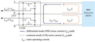
If we look at the interference signals from the EUT from the point of view of current flow, the return path for these may either be via the earth connection or via the ‘other’ line, see figure 1. The former type would cause the interference signal voltage on the two lines (live and neutral) to be in phase (this is the common mode situation) and in the latter case the voltages on the two lines would be opposite (differential mode).
Figure 1. Interference current flow
Mains filters can use up to 4 techniques to suppress interference. Many use a combination of two or more. These are:
· capacitors between the lines (live & neutral). The X capacitors. · capacitors between each line and ground. The Y capacitors. · Common mode chokes (each coils wound in same direction so that the flux created by the 50Hz power current (which is differential) will cancel and not saturate the core). · Differential mode chokes. Each line having its own choke.
The effect of capacitors is to tend to ‘short-out’ voltages at high (interference) frequencies. On the other hand, chokes offer a high impedance (resistance) at these frequencies.
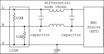
Figure 2 (a) Differential filter
Figure 2 (b) Common mode filter
Figure 2 shows the arrangement of each type of filter, in circuit with a LISN for measurement purposes.
Intuitively, if there is a common mode ‘problem’ connecting X type suppression capacitors across live and neutral would have very little effect because the interference voltages are already the same. It follows then that knowledge of the nature of the emissions will be of great help in selecting the optimum filter. It can also help in identifying the cause of the problem, offering then possibility of enacting a cure at source.
A Better Approach In order to obtain the measurements of common mode and differential interference signals we need to do more than is currently available in existing instruments. This problem has been addressed by Prof. Jung, Yong-Chaeof EMCIS in Korea. Laplace have been working with EMCIS to develop a new range of analysers that will incorporate this feature as standard.
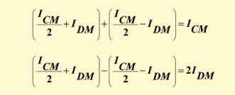
The common mode and differential mode voltage signals can be extracted by using a special circuit that measures both live and neutral emissions simultaneously and performs the following calculation.
With this system, a conventional EMC analyser or receiver can now display the three spectra of interest
· total emissions (as required by CISPR) · common mode emissions · Differential mode emissions
Obviously, to make these measurements, a LISN capable of outputting the interference signal from both lines simultaneously is required. Although some LISNs are already available that are able to do this, a new range of LISNs from EMCIS has now been introduced which will accommodate this feature as standard.
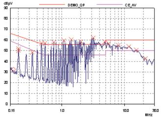
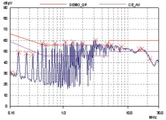
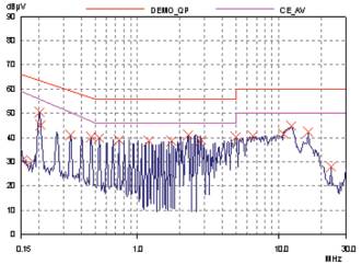
An typical example of these results is shown in figure 3
Figure 3 (a). Total noise
Figure 3 (b). Common mode noise
Figure 3 (c) Differential mode noise
These plots have been obtained from a Switch Mode Power Supply module (SMPS). The limits shown are EN55022.
The fundamental frequency of the power conversion can be deduced from the harmonic spacing and is about 70KHz.
It is immediately apparent that the emission level is unacceptable and that the problem is related to common mode noise. The differential mode noise levels, whilst significant, are within the limits. The choice of filter type required is therefore obvious. In this example, a combination of common mode filter plus a modification to the design (improved ground bonding) provided a complete cure.
Normal procedure when faced with a problem as shown above is to use trial and error techniques which can be time consuming and often leads to an over-engineered solution. Whilst this may be acceptable for prototypes and small batch products, the cost of unnecessary components and related assembly time represents wasted margin and profit.
The additional analysis provided by the Laplace instrumentation is estimated to have reduced the time required to obtain a cost effective solution several hours.
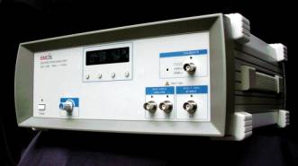
The Implementation There are two instruments which were introduced at EMV2002, Dusseldorf in Mid April. These are a conducted mode analyser, the EA2000 and a self contained EMC analyser, the ESA2000. The EA2000 is intended for use with any existing EMC analyser or receiver. Each mode (total, common or differential) can be output to the analyser in turn for measurement and display.
The ESA2000 includes the EMC analyser with Windows software for control from a PC. This provides a complete solution, taking signals from a LISN to and outputting the results on the PC screen/hardcopy/disk. The software includes all common limit and can display all relevant traces on screen simultaneously. The analyser covers the range 10KHz -1.1GHz, thus fully capable of covering the radiated EMC measurement requirements too. Options for both versions include an 8 section pre-selector for band B (150KHz - 30MHz). (The importance of a pre-selector cannot be overstressed if dealing with noisy broadband sources when using spectrum analysers for conducted emission measurements. See ‘Good Reason for Pre-selectors’, Approval Jan/Feb 1999).
In summary, the new technique offers an insight into the nature of your conducted emissions which can assist in problem location and filter specification, and provide compliance measurements too.
Figure 4. The ESA2000
David Mawdsley can be contacted on tel: +44 (0)1263 515160, Email: tech@laplace.co.uk or visit the website http://www.laplaceinstruments.com/
|