|
Feedthrough Filter Problems
Dr Jeff Chambers, Westbay Technology Ltd
Introduction Feedthrough filters utilise feedthrough capacitors, which have almost zero self-inductance. As a result the insertion loss, or attenuation curve, does not display a resonant peak, followed by a reduction in loss, as exhibited by axial leaded capacitors for example. High insertion loss up to the GHz region is provided, and the construction allows the filter to be mounted through a bulkhead, as shown below. The shielding integrity of an enclosure is not compromised as a result.
Most feedthrough capacitors utilise a ceramic dielectric, with a high dielectric constant (>3000) to achieve high capacitance per unit volume. Ceramic is a brittle material that can be cracked through mechanical and thermal shocks, which can lead to capacitor failure. Why should feedthrough ceramic capacitors cause particular problems compared with multi-layer chip (MLC) capacitors, which are used in their million? There are several reasons: MLC’s are small, are not soldered to solid metal parts, and are usually automatically placed and soldered. By contrast, feedthrough filters are relatively large, (allowing greater temperature gradients), contain ceramic capacitors soldered to solid metal parts, and are assembled and soldered to manually.
Many feedthrough problems are caused by poor handling practices by the user; others are caused by the user not revealing the entire operating specification to the filter manufacturer; others by the manufacturer failing to understand the implications of the specification; and finally some are caused by manufacturing defects or poor constructional standards. (Please note that none of the following is specific to any one filter manufacturer, and examples of all problems described could be attributable to the products of several manufacturers).
Filter Construction A few words about the construction of feedthrough filters and capacitors will help to understand the problem examples. Firstly, capacitor types. There are three geometries encountered in ceramic feedthrough capacitor technology. Tubular styles, discoidal styles, and planar array styles. The latter, used to provide multi-pin filtering in multiway connectors, will not be specifically dealt with here, although many of the comments regarding use of soldering heat, and so on, are equally valid.
Tubular capacitors use the inside and outside surfaces of a ceramic tube, to form a coaxial capacitor:
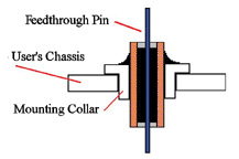
Capacitances up to 5nF are common, whilst multilayer tubulars are also found. Multi-layer pi-section capacitances up to 22nF are found, and capacitor-only types as high as 1 microfarad. Note that a pi-section split capacitor is achieved by splitting the metallisation inside the tube. A metal pin is passed through the centre of the tube, and soldered to the inner electrodes. A ferrite bead placed over the pin provides inductance. The outside common ground electrodes is soldered into a metal body or collar, for grounding to a bulkhead.
This is a cross-section of a typical solder-in pi-filter.
Discoidal capacitors meanwhile use a multi-layer construction to achieve a higher capacitance per unit volume:
Over-lapping ground and inner electrodes are sintered into one monolithic body, offering capacitances up to around 100nF in a nominal 5mm disc, and over one microfarad in a nominal 9mm disc.
Discoidal capacitors are again assembled to mounting collars, or threaded bodies:
A ferrite bead can be placed in the body to provide a C-L filter, as shown.
Having briefly covered the constructional styles, the outcome of feedthrough problems will now be mentioned.
Feedthrough Capacitors: Problem Outcomes Why discuss the outcomes before the causes? Because that is what the unwary user encounters first - the result of mishandling or whatever. The electrical outcome almost always observed when a ceramic capacitor fails, or begins to fail, is low insulation resistance between ground and inner electrodes. In a good part, insulation resistance will certainly exceed 1G ohm, and normally be above 40G ohms. In a part which is partly defective, this may fall to 100’s of M ohms - not usually a problem, but indicative of further future reductions which can eventually result in a short circuit in a fully defective part.
The above applies to both discoidal and tubular styles. A further electrical outcome in a tubular style occurs when the ceramic tube is so badly cracked, that one capacitor loses its ground connection, and the capacitance of a pi-filter halves.
There may be visual signs of damage on a feedthrough solder-in part, where the ceramic is visible, but otherwise there may be no signs when the filter is encapsulated with an epoxy resin for instance.
The problem areas themselves will be discussed next.
Feedthrough Problem Area One: Incorrect Feedthrough Termination Soldering Procedures This is probably the most common fault. A soldering iron is held to the feedthrough terminal of the filter for too long, causing microcracks in the ceramic. Over a period of time, the crack retains atmospheric moisture (even in an epoxy encapsulated part), and a conductive path begins to form, hastened by applied voltage. The part may remain indefinitely at the 100’s M ohm level, or may fall low enough to cause a circuit failure. This can take months, but is often detected if the host equipment must undergo a burn-in procedure.
The crack will often be internal in a discoidal capacitor:
It may be visible in an unencapsulated tubular capacitor, using an eyeglass or microscope:
Remedy: follow the manufacturer’s soldering recommendations. This will usually be to use a hotter iron for as short a time as possible, rather than a cooler iron held for longer. Whilst placing a heatsink clip between the part of the lead to be soldered and the filter body may seem a good idea, in practice there is little room on these filters.
Feedthrough Problem Area Two: Bending Feedthrough Terminations If a feedthrough termination is bent, without a mechanical support between the point of bending and the filter body, cracks as described above may well occur, with the same eventual outcome. Epoxy resin encapsulation should not be relied upon as a support. Some manufacturers will simply say that the terminations ‘are not for bending’.
Feedthrough Problem Area Three: Assembling Threaded Body Feedthrough Filters Feedthrough filters with threaded bodies typically use threads of M5 or M6 (12-32 UNEF, 10-32 UNF), and as such seem quite rugged little devices. There is a temptation to treat them as a nut and bolt - indeed, they are sometimes called ‘bolt style’ filters. DON’T! If the filter is over-torqued, it is quite possible to shear the body of the filter, just below the mounting shoulder, where the body wall is often quite thin. In addition, with a tubular capacitor construction, it is quite possible to crack the ceramic, with future insulation resistance problems, and also low capacitance.
Feedthrough Problem Area Four: Assembling Solder-in Feedthrough Filters Assembling solder-in filters, of the style shown below, poses special problems.
This style of filter has the advantage over the ‘bolt style’ of greater packing density, as clearance for the hexagonal body and assembly tool is not required. The disadvantage is that the chassis and filter must be heated to soldering temperature in order to solder it to the chassis, in practice to above 200C. A heating method should be chosen that provides a controlled and steady temperature ramp, with a similarly controlled temperature reduction. Temperature shocks should be avoided at all costs. Following soldering, the filters should be checked for signs of cracks.
There is a further issue here: what type of solder has been used in the filter construction? If you assemble the part to the chassis with ‘normal’ tin-lead composition solder (m.pt ~180C), and the filter pin and collar use the same solder, the filter joints will also reflow. This might not be a problem if the part is supported, but can result in off-centre pins for example:
Some lower cost ‘commercial’ filters do indeed use conventional solder. More costly parts use high melting point solders, melting between 220C and 300C.
Finally, a word about the number of solder-in parts assembled at one time. It is tempting to design large ‘arrays’ of filters, where large numbers of lines are to be filtered, perhaps in an avionics project for example. If there is a small chance of a filter cracking during assembly (1 in 500 say), there is clearly less chance of successfully building a 90 filter array, than a 10 filter array.
Feedthrough Problem Area Five: Incomplete Specification Provided to Manufacturer It is fair to say that as soon as a filter-related problem is identified, the filter manufacturer is contacted with the news that “One of your parts has failed”. It may be a manufacturing problem (see below), but the above handling issues must first be addressed. There is another scenario where a part fails, because it is being operated beyond its rated parameters. Areas which can particularly affect feedthrough filters include:
Transient Voltages: a power line specification may include transient voltages, originating for example from lightning-induced waveforms. It is vital that the filter manufacturer knows about these, and can show his parts can survive the transient. This applies to both tubular and discoidal parts, perhaps the latter more so.
Voltage Rating: ac voltages apply more stress than dc voltages, through the regular charge/discharge cycles. Equally, 400Hz ac is more stressful than 50/60Hz. If the manufacturer rates his part at 50/60Hz, it cannot be assumed that the part can be run at 400Hz.
Temperature Cycling Requirements: a component manufacturer will be required to demonstrate his parts can survive 10 or 20 cycles of temperature extremes (-55C to 125C for example). An avionic manufacturer’s equipment may need to be put through many more cycles, to simulate take-off and landing stresses. This will not normally be a problem, but there can be an issue with epoxy-resin sealed filters, where the epoxy has a much greater coefficient of expansion than the metal body. Cracks can form between the epoxy resin and the metal body, allowing moisture ingress.
Insertion Loss Specification: insertion loss is often specified at room temperature, zero applied voltage and zero load current. All three parameters can affect insertion loss. If the equipment operates over a wide temperature range, it may be important to specify an X7R temperature characteristic dielectric, which is much more stable than the Z5U characteristic. Applied voltage also lowers dielectric constant, and hence capacitance and insertion loss. Applied current causes ferrite bead inductors to saturate, also reducing insertion loss.
Feedthrough Problem Area Six: Manufacturing Defects No manufacturer will readily admit to producing defective parts. There is however a well-known potential manufacturing defect associated with any multi-layer ceramic capacitor, that of delamination of the multi-layer structure during the sintering stage of the manufacturing process. This creates a void within the part, which can in turn become a failure point. Much effort has been put into detection of delaminations by sectioning of sample parts. It is however very easy to introduce defects during sectioning, particularly when the ceramic part is soldered into a metal body.
There is one technique which is very effective in detecting inherent faults within feedthrough filters - burn-in. This consists of holding the part at a high temperature (125C), with an applied dc voltage (100Vdc), for a period of 24 to 168 hours. Some manufacturers make a virtue of this, offering 100% burn-in. Others offer it as required; either way, expect to pay more for the additional work involved. If your application is ‘high-rel’, consider a burn-in requirement. Military filter specifications such as MIL-F-28861 require 100% burn-in.
Summary Feedthrough filters are rugged items in operation, which require care in installation to avoid premature failures. Complete specification of operating conditions is required to obtain the correct part, and reliability for any particular application should be demonstrated.
Dr Jeff Chambers Further information on filter insertion loss effects can be found at: http://www.westbay.ndirect.co.uk/westbay3.htm
This article was previously published in the ITEM Update 2001. Visit the Interference Technology website at http://www.interferencetechnology.com/.
|