|
Standards for the Management of Potential Health Risks of EM Fields
By Tim Williams, Elmac Services and David Riley, Indexsar
Why measure SAR? · Concern about health effects from radio transmitters aggravated by widespread use of mobile handsets · SAR is universally accepted as a measure of energy deposition · Many regulatory agencies now require radio transmitters to meet SAR limits
For many years there has been concern on the part of the general public about the possible health effects of exposure to radio frequency (RF) radiation. High levels of RF field are known to cause a variety of physical effects on the human body. Although a relatively small group of radio users and technicians has been exposed by virtue of their occupations for many decades, with the dramatic increase in public use particularly of mobile telephones and latterly other wireless devices, it has become necessary to ensure that these products do not expose their users to potentially harmful levels of field.
At the frequencies of operation of most of these devices, the known health effects centre around tissue heating. A measure of this heating effect is known as Specific Absorption Rate (SAR). As part of worldwide efforts to legislate on consumer health and safety aspects, many authorities now require products, which are placed on the market to meet limits on SAR. Measurement of SAR is therefore becoming a fast-growing requirement for companies that make such products.
Potential Health risks of EM fields · ICNIRP guidelines: · Short-term immediate effects · Stimulation of peripheral nerves and muscles · Shocks and burns through touching conducting parts · Tissue heating due to energy absorption · Potential long-term effects · Increased risk of cancer: “available data are insufficient to provide a basis for setting exposure restrictions”
The basis for exposure on which most if not all regulatory limits are set, is laid down in the ICNIRP Guidelines*. This document refers to the known health effects. While induced circulating currents and externally generated RF shocks and burns are important in some situations, they are not relevant in the context of SAR measurement. For absorption of energy, EM fields can be divided into four frequency ranges:
· Frequencies from about 100 kHz to less than about 20 MHz, at which absorption in the trunk decreases rapidly with decreasing frequency, and significant absorption may occur in the neck and legs; · Frequencies in the range from about 20 MHz to 300 MHz, at which relatively high absorption can occur in the whole body, and to even higher values if partial body (e.g., head) resonances are considered; · Frequencies in the range from about 300 MHz to several GHz, at which significant local, non-uniform absorption occurs; · Frequencies above about 10 GHz, at which energy absorption occurs primarily at the body surface.
Low-level effects that may be experienced by some people but are not based on tissue heating (athermal effects) are still controversial and disputed, and are not covered by SAR limits.
GUIDELINES FOR LIMITING EXPOSURE TO TIME-VARYING ELECTRIC, MAGNETIC, AND ELECTROMAGNETIC FIELDS (up to 300 GHz), International Commission on Non-Ionizing Radiation Protection, Health Physics April 1998, Volume 74, Number 4:494-522
Tissue heating ICNIRP guidelines:
· Exposure for 30 minutes to a whole body SAR of 1-4 W/kg increases body temperature by less than 1°C · More intense exposure can give harmful levels of tissue heating · Hence the occupational exposure restriction is set at 0.4 W/kg (safety factor of 10)
To quote the ICNIRP document:
“Available experimental evidence indicates that the exposure of resting humans for approximately 30 minutes to EMF producing a whole-body SAR of between 1 and 4 W kg -1 results in a body temperature increase of less than 1°C. Animal data indicate a threshold for behavioural responses in the same SAR range. Exposure to more intense fields, producing SAR values in excess of 4 W kg -1, can overwhelm the thermoregulatory capacity of the body and produce harmful levels of tissue heating.
Many laboratory studies with rodent and non-human primate models have demonstrated the broad range of tissue damage resulting from either partial-body or whole-body heating producing temperature rises in excess of 1–2°C. The sensitivity of various types of tissue to thermal damage varies widely, but the threshold for irreversible effects in even the most sensitive tissues is greater than 4 W kg -1 under normal environmental conditions. These data form the basis for an occupational exposure restriction of 0.4 W kg -1, which provides a large margin of safety for other limiting conditions such as high ambient temperature, humidity, or level of physical activity.”
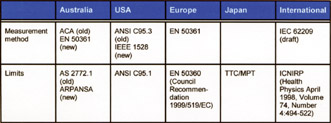
International regulations This table shows the principal regulations for protection of human health from electromagnetic fields worldwide. It also covers the SAR testing standards that are now coming into place to give effect to the regulations. The most significant of these are discussed in the following sections.
European regulations · Council Recommendation of 12 July 1999 on the limitation of exposure of the general public to electromagnetic fields (0 Hz to 300 GHz) (1999/519/EC) recommends basic restrictions · EN 50360: 2001 · CENELEC standard: Product standard to demonstrate the compliance of mobile phones with the basic restrictions related to human exposure to electromagnetic fields (300 MHz-3 GHz) · More to follow for other types of transmitter
The European Union put forward a Council Recommendation in 1999 which sets out the position that EU Member States are expected to take on EMF exposure limitation. This document recommends the basic restrictions given for the general public in the ICNIRP document. It also states
“In order to assess compliance with the basic restrictions provided in this recommendation, the national and European bodies for standardisation e.g. Cenelec, CEN) should be encouraged to develop standards within the framework of Community legislation for the purposes of the design and testing of equipment.”
CENELEC has developed such standards over the last few years; one of the first to appear was EN 50360: 2001 for mobile phones which refers to the Council Recommendation for SAR limits. This mandates the measurement methods of EN 50361, which we shall be studying in detail later. EN 50360 is a harmonised standard under the Radio & Telecommunication Terminal Equipment (R&TTE) Directive, meaning that any product which is marketed in the EU and which falls within the scope of this standard must comply with its requirements.
Others that had been harmonised at the end of 2002 are:
EN 50364: Electronic article surveillance (EAS), radio frequency identification (RFID) and similar applications EN 50371: Low power electronic and electrical apparatus EN 50385: Radio base stations and fixed terminal stations
US regulations · ANSI/IEEE C95.1: 1992: “Safety Levels with Respect to Human Exposure to Radio Frequency Electromagnetic Fields, 3 kHz to 300 GHz” gives limits which are referenced in FCC Rules
FCC rules: · 47 CFR §2.1091 (mobile, > 20cm) and §2.1093 (portable, < 20cm) · OET 65C gives guidance on the application of the FCC rules
As stated in the FCC rules, mobile and portable transmitting devices that operate in the Cellular Radiotelephone, Personal Communications (PCS), Satellite Communications, General Wireless Communications, Wireless Communications, Maritime (ship earth stations only) and Specialized Mobile Radio Service authorized, respectively, under Part 22 (Subpart H), Part 24, Part 25, Part 26, Part 27, Part 80, and Part 90 of the FCC rules are subject to routine environmental evaluation for RF exposure prior to equipment authorization or use. Portable devices operating in the Wireless Medical Telemetry Service (WMTS) and the Medical Implant Communications Service (MICS), authorized under Subparts H and I of Part 95 are subject to routine environmental evaluation for RF exposure prior to equipment authorization or use. Unlicensed PCS, U-NII and millimetre wave devices authorized under Part 15 of FCC rules are also subject to routine environmental evaluation for RF exposure prior to equipment authorization or use. All other mobile and portable devices are categorically excluded from routine environmental evaluation for RF exposure.
The FCC rules for evaluating portable devices for RF exposure compliance are contained in 47 CFR §2.1093. For these purpose, a portable device is defined as a transmitting device designed to be used with any part of its radiating structure in direct contact with the user’s body or within 20 centimetres of the body of a user or bystanders under normal operating conditions. Portable devices are evaluated with respect to SAR limits for RF exposure.
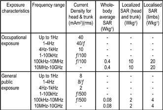
Basic restrictions
From ICNIRP, table 4 NB EC Council Recommendation 1999/519/EC uses the figures for general public exposure
Restrictions on exposure are based on established health effects and are termed basic restrictions. Depending on frequency, the physical quantities used to specify the basic restrictions on exposure to EMF are current density, SAR, and power density. Protection against adverse health effects requires that these basic restrictions are not exceeded.
Reference levels of exposure are provided for comparison with measured values of physical quantities (electric or magnetic field strength); compliance with all reference levels given in the ICNIRP guidelines will ensure compliance with basic restrictions. If measured values are higher than reference levels, it does not necessarily follow that the basic restrictions have been exceeded, but a more detailed analysis is necessary to assess compliance with the basic restrictions.
All SAR values are to be averaged over any 6-minute period. Localized SAR averaging mass is any 10 g of contiguous tissue; the maximum SAR so obtained should be the value used for the estimation of exposure. The lower basic restrictions for exposure of the general public take into account the fact that their age and health status may differ from those of workers.
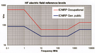
Reference field strengths
In many circumstances (though not in SAR evaluation of handheld transmitters) actually measuring SAR is either infeasible (because it would imply invasive measurements in a human body) or would not be economically justified. In these cases the fields to which people are actually exposed can be measured directly and compared to reference levels. It is important to note that these are not limits but levels at which investigation of the exposure regime should be initiated: provided that basic restrictions are met and adverse indirect effects can be excluded, these field strength values can be exceeded. Typical circumstances in which the reference levels are applied are in exposure of the public or workers to fields from base station transmitter installations.
Where appropriate, the reference levels are obtained from the basic restrictions by mathematical modelling and by extrapolation from the results of laboratory investigations at specific frequencies. They are given for the condition of maximum coupling of the field to the exposed individual, thereby providing maximum protection. The reference levels are intended to be spatially averaged values over the entire body of the exposed individual, but with the important proviso that the basic restrictions on localized exposure are not exceeded.
Reference levels are not relevant for handheld transmitters since the coupling takes place in the near field of the transmitting antenna. They are quoted here merely for comparison.
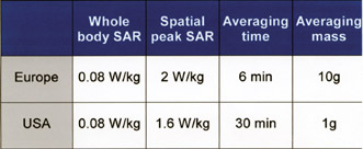
SAR limits The limits, which apply in general for mobile telephones and similar apparatus, are drawn directly from the applicable source document: ANSI/IEEE C95.1 for the US and a few other countries, ICNIRP for Europe and most of the rest of the world.
Two limits are used: a lower value for exposure averaged over the whole body, and a higher value which is applicable to local exposure to parts of the body (e.g. the head). This partial-body SAR is averaged over a volume of tissue defined as a tissue volume in the shape of a cube. The US requirements differ from the international requirements in their demand for a lower spatial average limit and that this limit is averaged over a smaller volume (1g of tissue as opposed to 10g). They also require a longer time over which the SAR is to be averaged; but since it is assumed that a user of a portable device will be exposed to the maximum power available from the device for the duration of the specified averaging time, in effect the requirement for time averaging of the output during SAR measurement does not apply. The whole-body SAR limit is assumed not to be exceeded if it can be shown – usually the case – that it is not exceeded over the measurement volume actually used, for portable devices which expose only a small part of the body.
SAR test standards · Europe – CENELEC: EN 50361: 2001: Basic standard for the measurement of Specific Absorption Rate related to human exposure to electromagnetic fields from mobile phones (300MHz - 3GHz) · USA – IEEE: P1528 (draft): Recommended Practice for Determining the Peak Spatial-Average Specific Absorption Rate (SAR) in the Human Body Due to Wireless Communications Devices: Experimental Techniques · International – IEC: EC 62209 (draft): Procedure to measure the Specific Absorption Rate (SAR) for hand-held mobile wireless devices in the frequency range of 300 MHz to 3 GHz
There are three main standards for the method of SAR measurement for mobile phones. These are shown above. EN 50361 applies to “any EM field transmitting devices intended to be used with the radiating part of the equipment in close proximity to the human ear”. IEEE P1528 applies to “certain hand-held radio transceivers used for personal wireless communications services ... contemporary and future devices that operate in the 300 MHz – 3 GHz frequency range and are intended to be operated while held next to the ear”. IEC 62209 is for “any electromagnetic field (EMF) transmitting device intended to be used with the radiating part of the equipment in close proximity to the human head”.
Fortunately, there is considerable common ground between the three standards. Coordination between the standards developing organizations, i.e. CENELEC TC106X, IEC TC106 and IEEE SCC34, has been achieved on specific issues by common membership on these committees. Test methods, procedures and assessment requirements are generally equivalent. The format of the IEC and EN documents is very similar, although there is more divergence between these and P1528.
SAR test standards · Scope, normative references and definitions · Measurement system specifications · Phantom · Measurement probe and equipment · Scanning system · Protocol for SAR assessment · Preparation · Measurement procedure · Post-processing · Uncertainty assessment · Measurement reporting requirement
Each of the three standards includes material on the above subjects in its main body, with minor variations in emphasis between them. The most important aspects are the requirements for the accuracy and performance of the test system, and the method of carrying out the measurements. An innovation in each of these standards is an explicit and detailed requirement for performing an assessment of the measurement uncertainty budget, and a limit on the maximum allowable uncertainty. This places requirements both on the equipment and on the laboratory’s procedures
Annexes Some of the more detailed and subject-specific material is relegated to annexes to the standards. This should not be taken to imply that it is less important; the annexes give crucial information both for the laboratory and for the supplier of the test system. An understanding of the whole standard, including its annexes, is necessary for its successful application.
The SAR measurement system Requirements of a SAR testing system · A phantom · A dielectric · A positioning robot · A measurement probe · Post-processing and control software · A validation check system
The SAR certification requirement Constituents of system · miniature probe, that is automatically positioned to measure internal E-field distribution, in a phantom model that represents a human head · SAR distribution and maximum mass averaged SAR value is calculated from these measurements
According to IEC 62209 draft para 5.1:
“The test shall be performed using a miniature probe that is automatically positioned to measure the internal E-field distribution in a phantom model representing the human head exposed to the electromagnetic fields produced by wireless devices. From the measured E-field values, the SAR distribution and the maximum mass averaged SAR value shall be calculated.”
Test systems should also include components for positioning the equipment under test and aligning the scanning system; for measuring the dielectric properties of the tissue simulant liquid; and for checking and validating the measurement accuracy.
Measurement geometries
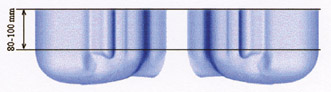
Full head phantom
Sagitally bisected phantom
The first question to be addressed is the nature of the phantom. It can be either an upright head model (top picture) or a dual sagittally bisected model, lying on its side (lower picture: the word “sagittal” refers to a join along the top of the skull between left and right halves).
Both the upright and horizontal twin SAM phantoms are permitted under the CENELEC and IEEE (FCC) standards, and the user must decide the trade-offs as they apply to their own products or customer base. The upright phantom is more convenient with lower liquid volumes, minimal evaporation issues with glycol based fluids and ease of device positioning. Advocates of the Twin phantom claim lower measurement uncertainty with axial versus hemispherical probe isotropic error and also reduced boundary effects. Implementation of each phantom is however specific to the complete system. Positioning errors and distortions caused by bulky device holders may offset measurement uncertainty benefits of the “Twin”.
The upright phantom requires more computational effort to convert the positioning data into the three-axis robot control commands, and requires a different phantom for flat surface tests and system validation, it is closer to the measurement intent of the standards and is generally easier to use in the laboratory. To minimise uncertainties it does rely on a probe with good isotropic response.
Block diagram of SAR system
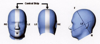
The SAM phantom The physical characteristics of the phantom model (size and shape) simulate the head of a user since the shape is a dominant parameter for exposure. The phantom is made from material with dielectric properties similar to those of head tissues. The shape of the Specific Anthropomorphic Mannequin (SAM) is derived from the size and dimensions of the 90 percentile large adult male reported in a 1988 US Army anthropometric study, adapted to represent the flattened ear of a wireless device user. CAD files of the inner and outer surfaces of the reference phantom are publicly available in 3D-CAD formats.
The shell of the phantom including ear spacer is made of low permittivity and low loss material, with a relative permittivity < 5 and a loss tangent < 0,05. The phantom shell shape has a tolerance of less than ± 0,2 mm with respect to the CAD file of the SAM. In any area within the projection of the handset, the shell thickness is 2 ± 0,2 mm, except for the ear and the extended perimeter walls. The ear spacer provides a 6 mm spacing from the tissue boundary at the Ear Reference Point (ERP) within a tolerance of less than ± 0,2 mm. In the central strip within ± 1,0 cm of the central sagittal plane the tolerance is relaxed.
Three points on the phantom are used to correlate with the positioning system. The point “M” is the reference point for the centre of mouth, “LE” is the left ear reference point (ERP), and “RE” is the right ERP. These points are used to give reproducible positioning of the EUT against the phantom.
The dielectric liquid The phantom must contain a liquid whose dielectric properties are chosen to simulate human tissue – brain tissue for head measurements or body tissue for EUTs that are body-worn. The liquid allows the probe to move freely within the phantom inner volume. Because these properties are frequency-dependent, a different liquid must be formulated for each test frequency band. The standards give specific requirements for s and e for each frequency. Since recipes for ingredients don’t give exactly correct values, partly because of inaccuracies in mixing and partly because of variations in the properties of each ingredient, the actual values (rather than the standard specification) must be measured and used in the testing. There are three accepted methods for measuring the dielectric properties, of which the TEM line is the most accurate; this uses a vector network analyser.
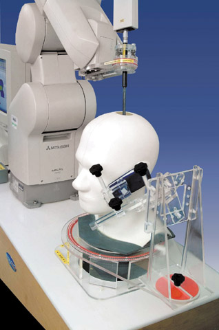
The positioning robot and holder
The robot system holding the probe has to be able to scan the whole exposed volume of the phantom in order to evaluate the three-dimensional SAR distribution, without interfering with the SAR measurements. The accuracy of the probe tip positioning over the measurement area must be better than ± 0,2 mm The positioning resolution – the step size at which the measurement system is able to perform measurements – should be 1 mm or less.
The EUT holder must permit the device to be positioned according to the standard definitions with a tolerance of ± 1° in the tilt angle. It should be made of low loss and low permittivity material(s): loss tangent <0,05 and permittivity < 5 phantom shell. Unfortunately for a mobile phone holder, this is not a sufficient criterion. It is known that even low-loss plastic materials in the vicinity of certain types of handset antenna can have big influences on the SAR measurements. The requirement is to minimise the product of volume and loss (or relative permittivity) in structures close to the handset. Large, solid holders may help with positional repeatability but could introduce larger uncertainties due to materials influences.
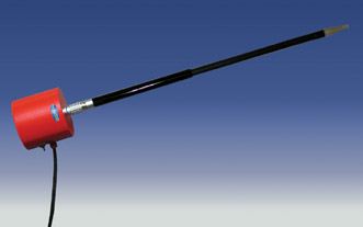
The measuring probe
There are several important parameters to the measuring probe. It must be small enough to have no resonances over the frequency range of interest and so as to allow a precise spatial registration of the field. It must also not disturb the field structure in the liquid significantly. The measurement centre should be as close to the tip of the probe as possible, to minimise the “dead volume” next to the phantom shell that cannot be measured directly. The standards recommend that the probe diameter should be no more than 8mm; most systems have probe tip diameters of around 5mm. These features are provided by using very small, short dipole elements with integral diode detectors at their centre, and taking the DC output from the diodes to a remote amplifier through high-resistance leads which are transparent to RF.
The probe must also be sensitive, linear and isotropic. The minimum detection limit should be < 0.01W/kg and the maximum should be > 100W/kg. Within this range the linearity should be ±0.5dB.
Calibrating the probe
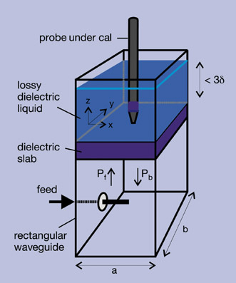
To calibrate the probe it is necessary to apply a known SAR into the same dielectric liquid as will be used for the test. This can be achieved using the waveguide method. The SAR developed in a liquid-filled rectangular waveguide can be calculated as follows:
Where: - z is the longitudinal distance from the dielectric separator- a, b are the waveguide dimensions
· Pf and Pb are the forward and reflected power in the lossless part of the waveguide · the density r is taken to be 1000 kg/m3- d is the penetration depth in the liquid, determined theoretically and confirmed by measurement
This method is the basis for providing an accurate calibration traceable to national standards for the probe.
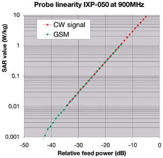
Probe linearity
Since the diode detectors used are non-linear – they respond to the square of the field at low levels, reducing to a direct proportionality at higher levels – a linearisation process must be carried out on each of the three channels independently, in the measuring electronics. The linearisation must be matched to each individual detector.
The probe channel output signals are linearised using the following equation for each channel (x, y and z):
Ulin = Uo/p + Uo/p 2 / DCP
Where Ulin is the linearised signal, Uo/p is the raw output signal in voltage units and DCP is the diode compression potential in similar voltage units. DCP is determined from fitting this equation to measurements of Ulin versus source feed power over the full dynamic range of the probe.
Different calibration factors are needed for pulsed signals. At each power level, the individual channel outputs from the SAR probe are recorded at CW and then recorded again with pulsed modulation. The modulated power is calculated by applying a factor to the measured CW power (e.g. for GSM, this factor is 9.03dB). The DCP value for linearising each of the individual channels is assessed separately and listed in the summary page of the calibration factors for each probe.
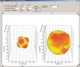
Probe isotropy Probe isotropy is the degree to which the response of the probe is independent of the polarization and direction of propagation of the incident wave.
Axial isotropy is defined as “the maximum deviation of the SAR when rotating the probe along its main axis with the probe exposed to a reference wave impinging from a direction along the axis of the probe”.
Hemispherical isotropy is “the maximum deviation of the SAR when rotating the probe along its main axis with the probe exposed to a reference wave with varying angles of incidences with regard to the axis of the probe in the half space in front of the probe”.
Isotropy checks can be performed in the calibration waveguide or in a jig which rotates the probe about the relevant axis.
The diagrams above show the probe response to fields applied from each direction: the diagram on the left shows the individual response characteristics of each of the three channels and the diagram on the right shows the resulting probe sensitivity in each direction. The lowest values are blue and the maximum values are red. For this probe, the range is ± 0.43 dB.
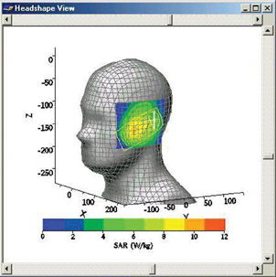
Control and post-processing The software package in a SAR measurement system has several important functions. It must decide the actual measurement grid based upon input from the test operator and knowledge of the shape of the phantom shell. This grid must then be used to control the position of the measurement probe through the positioning robot. The test operator has the opportunity to modify the geometrical data (grid position and spacing) before the control process. Registration of the probe position in relation to the shell is a vital part of this process. The software algorithm has to derive the expected worst-case locations within the phantom in the area of the EUT by interpolation and extrapolation from the initial results, and then control the three-dimensional final scan. Having acquired the final values within a limited volume, the spatial average and maximum levels then have to be calculated according to the methods allowed in the standards.
The standards do require that the software’s calculation algorithms are validated, i.e. that they produce correct results from a set of known input data. Four separate data files are available with the standards, with correct reference output values, to achieve this.
Last but not least, the software must interface with the test operator in a user-friendly way. Visual representation of key stages of the process is important.
Validation and system check · Reference source needed to confirm measurement accuracy · Uses separate simplified phantom and reference dipoles driven from known CW power
The systems check set-up proves the operation and accuracy of the probe and positioner, and the correct composition of the liquid dielectric. It is performed before a compliance test at a frequency within ±10% of the test frequency, and the result must be within ±10% of the target value of a 1 or 10g averaged SAR.
The target values are provided in the standards through calculation with specific phantom properties and separation distances. The validation system uses a flat phantom and the target values are listed for 1W power into reference dipoles of specified design. Thus validation tests the accuracy of the measuring probe and electronics, but not of the mechanical registration of the real phantom and scanning system.
For further information please contact David Riley driley@indexsar.com
Tim Williams can be contacted by email at: elmactimw@cix.compulink.co.uk
This article also appears on the IEE website at: www.iee.org/oncomms/pn/emc/SAR.pdf
|