|
Shortcomings of Simple EMC Filters
By Jan Nalborczyk, Technical Director, MPE Limited
Synopsis Oversimplification of filter selection to reduce size and cost can often be a false economy as anticipated performance may not be achieved.
Introduction EMC design principles are best considered at the equipment design stage where good mechanical design including component layout and cable routing can help reduce EMC problems at source. Even with good EMC practice, it is invariably necessary to provide a certain amount of filtering. Cost and size considerations will usually encourage the use of a simple filter design. This can sometimes be a false economy as simple designs may not always give expected results. This can have serious compliance implications if EMC specifications have to be met. Some of the commonly encountered problem areas and their solutions are discussed here in this article.
Problems and Solutions When using suppression capacitors either on their own or in filters, it is most important to keep lead lengths as short as possible.
An ideal capacitor of capacitance value C, would have a linear impedance characteristic, Z given by
where f is the measurement frequency.
However, a real two-terminal capacitor will resonate at a frequency determined by its capacitance and the inductance, L of its leads. The resonant frequency is given by
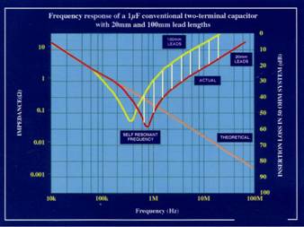
Below the resonant frequency, the capacitor impedance follows the ideal response, but above the resonant frequency, the capacitor suppression performance reduces dramatically. Increasing the lead length reduces the resonant frequency and causes a loss in performance of the capacitor. This can be seen in figure 1 which compares the impedance of a 1µF capacitor with 20mm and 100mm leads. The leads of a two-terminal capacitor will typically have an inductance of about 7nH per 10mm, which gives a resonant frequency of about 800kHz for a 1µF capacitor with 20mm leads. The shaded area indicates the loss in performance caused by increasing the lead length from 20mm to 100mm.
Figure 1: Frequency response of a 1mF two-terminal capacitor with 20mm and 100mm leads
Above its resonant frequency, the two-terminal capacitor behaves as an inductor with the inductance L, of its lead wires. Its impedance then becomes Z = 2πfL. If suppression performance is needed above the resonant frequency in line to earth applications, then a feedthrough capacitor must be used. Apart from a few minor resonances related to the dimensions of the capacitor element, the feedthrough capacitor has a performance close to the ideal capacitor performance.
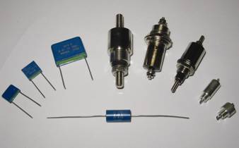
Figure 2: Typical feedthrough capacitors compared with two-terminal capacitors
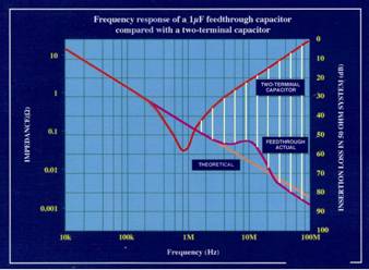
Figure 2 shows the physical differences between two-terminal capacitors and feedthrough capacitors. Figure 3 compares the performance of a 1µF feedthrough capacitor with a 1µF two-terminal capacitor. The shaded area shows the significant performance not attainable from a two-terminal capacitor, which can be gained by using a feedthrough capacitor of the same value.
Figure 3: Impedance and insertion loss performance of 1µF feedthrough capacitor compared with a 1µF two-terminal capacitor
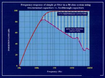
For the same reason, good high frequency performance in filters can only be obtained if the filter incorporates feedthrough capacitors. As an example, figure 4 shows the insertion loss performance of a simple dc pi filter built with feedthrough capacitors, compared to the same filter built with two-terminal capacitors. The shaded area indicates the extra performance obtained by using feedthrough capacitors in the filter design. Note that this graph is displaying insertion loss as opposed to impedance on previous graphs so is plotted in the more usual direction for insertion loss.
Many existing EMC specifications only specify equipment emissions requirements up to 30MHz, and usually, a filter containing two-terminal capacitors will be adequate to comply with these specification requirements. Newer specifications are now demanding susceptibility performance up to 2GHz or beyond. This is to provide some protection against the effects of increased high frequency noise pollution generated by faster processors, mobile phones, faster power control switches, and so on.
The user should be aware that even if his equipment has a CE mark to demonstrate compliance with existing EMC specifications, he could still experience problems. Unless his equipment is fitted with a suitable high frequency filter containing feedthrough capacitors, it is unlikely to be protected against incident high frequency interference above 30MHz. He could still therefore be responsible for problems caused by his equipment malfunctioning as a result of susceptibility to high frequency interference.
Figure 4: Performance of simple dc rated pi filter built with and without feedthrough capacitors
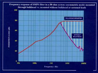
Even when using feedthrough capacitors, performance can be compromised if the filter or capacitor is not mounted correctly to suitably screen the input from the output terminals. By-pass coupling due to radiation and pick up on interconnecting wires is more pronounced at higher frequencies, so greater care is needed to avoid this. The filter should ideally be mounted on or through a bulkhead to completely isolate input from output cables. Alternatively, screened cables should be used on one or both sides of the filter to prevent coupling. Figure 5 shows the effect of not mounting such a filter on a bulkhead or using screened cables. The shaded area shows the loss in high frequency performance when the filter is not mounted or screened correctly.
Figure 5: Performance of a mains filter with feedthrough capacitors correctly mounted compared to being installed without bulkhead or screening
Electromagnetic Interference Electromagnetic Interference (EMI) occurs in two modes, asymmetric between line and earth, and symmetric between lines. Suppression components fitted to remove one mode of interference may have little or no effect on the other mode, which requires a separate set of components connected differently. When choosing a filter circuit, it is important to know whether only one, or both modes of interference require suppression, so that a filter containing the necessary circuit components can be selected.
Asymmetric filter performance requires common mode inductors and capacitors from lines to earth, whereas symmetric mode performance requires single line inductors and capacitors between lines.
Where single line inductors are used in filters, they will saturate as load current increases and performance will be lost. The user should always check to see that performance figures quoted relate to full load conditions, as performance at full load current can be a lot worse than no load performance.
In most filtering applications, some asymmetric performance is normally required across the frequency spectrum up to 1GHz. Symmetric performance, where needed, is usually only required below about 10MHz. Some symmetric performance is often provided by board level components.
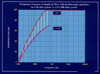
The insertion loss performance of filters and suppression components is always quoted in a 50Ω system. This has traditionally been considered to represent the characteristic impedance of power lines at radio frequencies. With the widespread use of switching power supplies and power controllers, a much lower source impedance is now more typical. In such cases, a different performance will normally be provided by the suppressor or filter compared to the 50Ω performance shown in the catalogue or data sheet. For most simple filters used in these applications, the actual performance obtained will be worse than expected. Figure 6 shows an example of the performance of a simple pi filter in a 50Ω system compared with that measured in an impedance of 0.1/100Ω (0.1Ω source and 100Ω load impedance) which might be more typical for a switched mode power supply. The shaded area shows the significant loss in performance produced in the practical system compared to the quoted 50Ω figures. Although the graph shows a filter with feedthrough capacitors as an example, a filter using two-terminal capacitors would show a similar reduction in performance in the different impedance system. To obtain the required performance in the practical system, it is necessary to tailor the filter circuit to obtain a maximum impedance mis-match between the filter and the system impedance. This usually means using a filter with an inductive input to face a low impedance noise source.
Figure 6: Frequency response of a simple dc rated pi filter with feedthrough capacitors in a 50W system compared to a 0.1/100Ω system
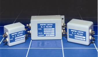
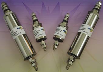
Standard Ranges There are many types of simple circuit filters available from many manufacturers, but most of them could be subject to some of the problems described above when used in certain applications. Becoming increasingly important are standard ranges of feedthrough capacitors, and filters incorporating feedthrough capacitors, which are designed to address some or all of the above problem areas. Some of the standard ranges of filters now available not only incorporate feedthrough capacitors but also have filter circuits designed to give the best response with low source impedance. Some manufacturers’ catalogues now quote performance in both 50Ω and 0.1/100Ω systems, which is more helpful especially where the application has low noise source impedance. Figure 7 shows an example of standard filters incorporating feedthrough capacitors, and which have bulkhead mounting to provide optimum high frequency performance. As an alternative, figure 8 shows an example of standard ranges of feedthrough capacitors, which will offer excellent cost-effective high frequency performance where the performance of a full filter circuit is not needed.
Figure 7: Standard range of equipment filters incorporating feedthrough capacitors
Figure 8: Standard ranges of feedthrough capacitors
Summary This discussion has identified a few pitfalls, which can cause the anticipated filter or suppressor performance not to be achieved in practice. If a standard catalogue filter is to be used, then the user should ensure that the selected filter design addresses any of the above problem areas, which may be relevant to the application. This may involve the selection of a slightly more specialised filter. For critical applications, the best approach is to obtain advice on the selection of the best filter circuit to use from a specialist filter company with established practical experience in filtering for EMC. They should be familiar with the type of problems discussed above, and should therefore be able to provide rapid and accurate advice on the most cost-effective solution for a given application.
MPE offer a technical helpline for free advice on +44 151 632 9199 and free catalogues and application notes for guidance are available for download from their website on http://www.mpe.co.uk/.
MPE is a member of the EMCIA, http://www.emcia.org/.
|