|
EMC: the hidden enemy of your equipment Manage it and turn it into a friend By Christophe Dognon, ERA Technology Ltd
Introduction Today’s typical installations comprise a wide variety of equipment. One of the main changes compared to a few decades ago is the boom in IT and telecommunication equipment, and components in traditional equipment or tools. A car factory probably uses the same basic tools to build cars (e.g. presses, spray equipment, welding equipment, lathes etc.) as twenty years ago, but all these tools now contain micro-processors, sensors, and remote control gear, and most are computer controlled.
This major technological change means that the range of issues to consider for asset failure management has evolved considerably. Where mechanical failures were usual in the past, nowadays equipment fails mainly due to electrical/electronic problems.
The increase in electronic component density in equipment, associated with an increase in clock frequencies and a more and more polluted electromagnetic environment, lead to a higher risk of equipment electrical failures, sometimes with implications on functional or personal safety.
A considerable part of these failures is due to electromagnetic compatibility (EMC) problems, although it is often difficult to determine. The major problem with EMC is that in most cases the physics associated with EMC cannot be sensed. To resolve a difficult EMC problem often requires the involvement of an external expert at some additional cost, so that it is common practice to replace the failed equipment without exploring the cause of the failure. Will the new item work where the old failed? Finger crossed !
This article briefly describes the basics of EMC, both from a technical and legal viewpoints; provides some examples of real life problems that have occurred and have been explored; and finally provides guidance on how EMC should be managed in order to minimise risks.
EMC basics EMC is the ability of an equipment to work satisfactorily in its electromagnetic (EM) environment without introducing intolerable electromagnetic disturbances to anything in that environment.
There are two points of view from an item of equipment:
· Emission: the system is considered as a source of disturbance
· Immunity: the system is considered as a potential victim of disturbance
These two aspects are not exclusive: an item of equipment can be the source of one type of disturbance and be the victim of another type of disturbance.
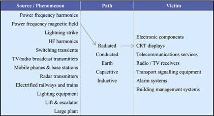
Technical considerations EMC is a source – path – victim problem. The table below lists some examples of these three aspects.
Interference occurs when it is possible to link a source or phenomenon to a victim via a path and the emission levels from the source exceed the maximum tolerable level of the victim. For example, as shown in the table above, high levels of power frequency magnetic field radiating close to CRT displays may cause the displays to distort, causing visual fatigue to operators, who can even miss safety critical information displayed on their system.
In order to reduce the risk of interference to acceptable levels, there are three possibilities: a) reduce the level of disturbance due to the source; b) remove the path or provide higher attenuation in the path by shielding or filtering; c) increase the immunity of the victim. It will be, and is almost always the case, a compromise between the three basic solutions that lead to an effective risk mitigation. It should be noted that solutions a) and b) are sometimes not practically achievable. For instance, airport operators cannot be required to reduce radar output powers, or in case of conducted coupling, the disturbance source cable may not be removed nor screened and has to stay as it is. Therefore, solution c) is more often used when an identified interference problem needs to be fixed. Conversely, during the design stage, i.e. when using a proactive approach to EMC, there are more opportunities to also implement solutions a) and/or b).
Legislation The legislation on EMC is based on the European EMC Directive [1], enforced in the UK by the Statutory Instrument SI2372 [2]. The Directive lays down essential protection requirements in broad terms, and leaves the task of defining specific technical requirements to the European standards making bodies: CEN, CENELEC and ETSI.
The Directive mainly divides equipment (in the broadest sense) into two classes:
· Apparatus or systems that can be sold on the European market as single commercial units. These items need to be tested to defined EMC harmonised standards (when they exist) and a Declaration of Conformity (DoC) needs to be produced with the documentation accompanying the equipment. The equipment must also bear the CE Mark. Some equipment, such as passive systems (e.g. cables), or products covered by other directives such as the Automotive EMC Directive are excluded from the EMC Directive 89/336/EEC.
· Fixed installations, which are defined as “a combination of several equipment, systems, finished products and/or components (hereinafter called parts), assembled and/or erected by an assembler/installer at a given place to operate together in an expected environment to perform a specific task, but not intended to be placed on the market as a single functional or commercial unit” [3], need only to satisfy the Directive essential requirements. No test to standard needs to be performed, due generally to the large size of fixed installations. No DoC is to be produced, nor any CE Mark to be put on the installation. However, the UK EMC Regulation SI2372 requires that some documentation be provided in order to show that all reasonable steps have been taken to satisfy the essential requirements (see section on EMC management).
There are various sets of EMC standards, which installations operators and asset managers should be aware of:
1. Product standards and product family standards state which emission limits and/or immunity levels, and which measurement methods, should be applied to a specific type/family of equipment. For instance, EN50091-2 applies to UPS, both for emission and immunity requirements.
2. When, and only when, no product/product family standard exists, then generic standards apply. They again define the requirements as above. Two environments are defined, the residential / commercial / light industrial on one hand and the heavy industrial on the other hand (see [4] and [5] for the definitions).
3. The basic standards that are referred to by the product and generic standards, describe the various test methods to apply.
The standards in item 3 above should be considered as reference standards, as opposed to product qualification requirements standards as in 1 and 2. It should also be noted that in addition to the product and generic emissions and immunity standards mains operated equipment must comply with standards for mains harmonics (EN 61000-3-2) and voltage fluctuations (EN 61000-3-3).
Real life “EMC failures” This section provides a few examples of failures or malfunction of equipment due to EMC problems. These examples show that the consequences can sometimes be very important, from a financial and/or safety point of view.
Examples These examples are taken from the UK EMC Journal, in a section called “Banana Skins”. They can be found on the journal’s web site [6], along with many other examples and EMC articles (all free!).
1. The HSE recently prosecuted the supplier of an item of equipment, which led to a release of chlorine in a semiconductor plant. The equipment was not sufficiently immune to mains transients (and proven to be so by our own labs). We prosecuted under section 6 of the Health and Safety at Work Act because the supplier, though aware of the problem, did not inform the users of the equipment. The company pleaded guilty. (From Simon Brown of the HSE, 13th January 1999)
The case referred to was the prosecution of Fluid Systems International (t/a Cambridge Fluid Systems) at Swindon Magistrates Court on November 25th 1998. The defendant entered a plea of guilty to a charge brought under S6 (1) (d) of the Health & Safety at work etc. act , 1974. The magistrates imposed a fine of £5,000 and made an order for the defendants to contribute £7,000 towards HSE’s costs of £9,482. The case concerned a microprocessor based valve control panel used to control the flows of chlorine and nitrogen in a semiconductor plant. There had been a release of chlorine resulting from all of the valves in the control cabinet being set to an open position. Investigation by the HSE found that the unit was susceptible to conducted transients on the mains supply. There were no precautions against electrical interference in the power supply and the microprocessor watchdog was not effective in ensuring a safe state following detection of a fault. The HSE inspector who dealt with this case was Eifion Davies in our Cardiff office. (From Simon Brown of the HSE, 3rd March 1999)
2. A 1.5 MW induction furnace controlled in on/off time-proportioning mode (using large contactors to switch the current) interfered with the computers in a Marks and Spencers store half a mile away. (From Laidler Associates Consulting Services, June 1998)
3. A large manufacturer of industrial fasteners, negotiating with a major customer, agreed to install a packaging cell containing an automatic weighing machine, which filled plastic packets with fasteners and an RF welding machine to seal the packets. For cost reasons the two machines were purchased separately. No assessment of the electromagnetic environment took place, and the machine contract specifications included no EMC requirements other than “shall meet all legal requirements”.
Both machines were supplied, installed, and tested successfully. Unfortunately when both were operated together the weighing machine suffered >25 % errors due to interference from the RF used by the welder (not an uncommon problem). In an 8 hour shift the cell should have packaged £20,000 of fasteners, but could have given away up to £4,000 of product in incorrect weights.
There was no comeback on the machine suppliers, whose products met specification. Both suppliers appeared willing to help, but when pressed blamed each other. Expert technical assistance was brought in and solved the problem. The fastening manufacturer lost 6 weeks production, suffered additional costs, and lost credibility with their major customer.
From the paper “The real engineering need for EMC” by John Whaley, General Manager of SGS International Electrical Approvals (UK).
4. There was a minor collision between a supply vessel servicing a semi-submersible offshore oil and gas installation. The vessel experienced a sudden power increase brought on because of interaction between radio signals from a portable VHF radio and the joystick control. This caused the joystick to execute commands not requested by the operator and resulted in contact between the vessel and the installation. The interaction caused minor damage (though it could have been far worse).
The incident occurred outside UK waters and was reported in a safety notice issued by an offshore operator. The safety notice was seen by an HSE inspector on a bulletin board on an offshore installation, dated 30 September 1999, which referred to the incident as having happened ‘recently’. (from Simon Brown of the HSE, 14th and 15th February 2000)
5. Poor power quality costs businesses in Europe €13-20billion a year, the European Copper Development Association estimates. This is the first attempt to pin down the cost in Europe of voltage deviations, transients, interruptions, and harmonics, says the organisation. These problems are increasing because of the growing use of equipment such as switch-mode power supplies, variable-speed drives, and high-frequency lighting, it adds. The use of such polluting equipment means that 70-80% of power quality problems are caused by operations on sites, rather than by external effects, says the institute. Problems produced by poor-quality power include glitches in computers, burnt-out motors, failed transformers and fires caused by high neutral currents. (From Electrical Review, 4th July 2000, page 3.)
6. Silicon Film Technologies, the firm developing a digital ‘film’ that fits in a standard SLR camera body, has suspended operations because of failure to meet EMC standards. “The failure of certification tests in the summer delayed Silicon Film’s anticipated revenues, but development expenses continued,” said Robert Richards, president and CEO of Irvine Sensors, the firm’s largest creditor. Last week Silicon Film said it had met the FCC emissions requirements but could not conform to the stricter European standards. “We believe at least some of those stricter standards must be met for a successful product launch,” added Richards. If alternative finance is not found, the firm – 51 per cent owned by Irvine Sensors – will go onto liquidation. (From Electronics Weekly, 19th September 2001.)
7. Offshore oil and gas production platforms present an extremely difficult electromagnetic environment due to the amount of electrical and electronic devices crammed into a small space. In this case, a platform was anchored to the sea bottom, but its exact position was adjusted by thrusters, i.e. large electric motors driving propellers. The position of the platform was controlled by a computer system. The power and control cables, all screened, were routed from the control room on the bridge at the top of the platform, all the way down to the engine rooms far below. However, the cable feedthroughs were not protected against electromagnetic disturbances. Com radios were used both on board the platform and for communication with land.
When a technician tried to use his com radio in the engine room, the connection was continually bad. By letting the radio antenna touch a cable harness, the connection became much better. By feeding its electromagnetic energy into the cable screens, the radio got a much improved “antenna”. Unfortunately, the energy in the cable screens also went elsewhere. It went via the cable screens to the thruster control equipment, which interpreted the energy as a signal for adjusting the position of the platform. (From Roxtec Ltd, page 22 of its booklet on ‘Cable and pipe transits for EMC’, December 2002, www.roxtec.co.uk)
What to do in case of equipment EMC failure As mentioned previously and shown in the above examples, it is not often easy to determine the cause of equipment failure or malfunction when the cause is EM interference. Moreover, EMC trained or skilled engineers are not often employed by installations operators. It is therefore a good idea to think of EMC when other obvious causes of failure can be discarded, i.e. when a bit of mystery persists on the very cause of the failure.
If EMC is really the cause, an EMC expert, or an in-house electrical engineer with some EMC training, should be able to determine it and then provide solutions. A few usual mitigation measures are listed below, but of course a specific assessment must be undertaken before implementing any measure:
1. Change the technology of the victim equipment: for instance, LCD screens, as opposed to CRT screens, are not susceptible to high magnetic field levels.
2. Reduce or remove the source: for example, mobile phones are nowadays a major source of disturbance to many types of equipment. In sensitive areas, the restricted use, or even prohibited use of mobile phones is the only sensible solution to apply (e.g. in hospitals and data centres).
3. Apply shielding techniques to the victim equipment or room enclosing the source or victim equipment. This technique needs to be implemented very carefully, due to the high costs often involved, and to the fact that any defect may cancel all the efforts put in the shielding. For example, shielding an equipment cabinet does not consist only in joining six steel or aluminium panels together, but also in adding EMI gaskets to the door, shielded windows to displays, and properly bond the whole lot to a well engineered earth bar. It should be noted that protection measures should apply also to all cables entering or exiting an equipment or its enclosure, in the form of glanded cable shield terminations, surge protective devices and filters.
4. Use shielded cables, or fibre optic cables. Again, the above caveat apply. It is not sufficient to purchase high quality screened cables, their layout and screen bonding techniques are important as well.
5. Change the position of equipment. For example, very high currents are carried by support structures and down conductors in buildings in case of a lightning strike. It is recommended not to put sensitive equipment in the rooms at the periphery, but instead in the rooms at the centre of the building.
The examples in the previous section show that the cost of fixing EMC problems is generally high, but the operational costs due to failures are even higher, since a failure often means that the installation has to stop its operation, or to operate at a slower rate. Moreover, legal action can be taken by government authorities or by private individuals or companies, leading to financial penalties.
This is why a proactive approach to EMC is considered as the best option to reduce the number of failures, hence the operating costs of the installation.
EMC management For assets managers there are several aspects of EMC management which must be taken into account. The combination of these aspects, described below, leads to effective asset management and demonstrates due diligence in case of EMC-related events thus avoiding unwanted legal action.
Specify EMC for asset procurement All relevant equipment to be purchased must be compliant with the EMC Directive and the associated harmonised standards. Although it is not mandatory to state it in the technical specifications for the project, since the suppliers have to comply anyway, it is highly recommended in order that the compliance of supplied equipment can be independently verified. What is even more strongly recommended is to define the type of environment in which the equipment is to be installed. The set of standards to be applied may vary according to the EM environment in which the equipment is intended to operate. Installing a PC in an office or in a plant room is not the same thing and does not have the same EMC consequences. The suppliers have to know that in order to deliver the right item of equipment to the right place.
Equipment must be supplied with an adequate DoC, and EMC information in the O&M or User Manual where necessary. The DoC must be kept in a safe place because this is the proof that the equipment is compliant. It goes without saying that the manufacturer’s instructions in the O&M Manuals must be followed. In case of any doubt or conflict with other instructions, then help should be sought, first from the manufacturer, then from experts when necessary.
Implement EMC installation best practice Installation operators and owners should have a set of EMC guidelines that are suited to their installation and covering such topics as cabling, earthing and bonding, shielding, filtering, equipment layout, etc.. These guidelines should also describe the EMC environment in each part of the installation, so that they can be provided to installers, maintenance operators, etc. whenever needed. This avoids a local contractor making mistakes when installing new equipment because, for instance, they are not aware of the neutral earthing arrangement or the type of bonding network used in this particular installation.
Moreover, this type of guidelines ensures consistency across the installation and during the installation life-cycle.
Define an EMC management strategy In an analogy with athletic events, EMC management is closer to a marathon than a 100m sprint (generally it’s a 100m sprint when something goes wrong, exactly the opposite of what is presented in this section). Therefore, there is more to EMC management than procurement and best practice issues.
EMC should be seen by asset managers as part of the global QA process. Therefore, procedures should be set within the QA system, which cover such topics as:
· Who is responsible for EMC: how many persons, skills required (not the same in a data centre or in an oil refinery). · How EMC is recorded: failures, upgrades, maintenance checklist, etc. · What programme for EMC is defined and effectively implemented: schedules for maintenance, design reviews for installation upgrades or modifications for example. · What the EMC environment is in the installation(s). Care must be taken for managers of several installations, since the environment may change even if the equipment within each installation is the same: presence or not of cellular radio base stations, proximity to an airport, etc.
Don’t forget that EMC and safety are closely linked! The examples presented in this article clearly show that EMC failures (can) have a major impact on functional safety, or even personal safety. However, complying with the EMC Directive or any of its associated standards does not automatically imply that all safety aspects are sufficiently covered. It is therefore essential to refer to other appropriate standards, such as the EN 61508 series [7] to ensure that safety aspects of equipment are adequately covered. The technical report DD IEC 61000-1-2 [8] also provides very valuable information on how to achieve functional safety related to EM phenomena.
It should also be noted that some EMC guidelines may conflict with safety requirements in some very specific circumstances. In this case safety always prevails over EMC.
References [1] EC Directive 89/336/EEC 3 May 1989 on the approximation of the laws of the member states relating to electromagnetic compatibility [2] The Electromagnetic Compatibility Regulations Statutory instrument 1992 No 2372 + Amendment No 3080 1994 [3] European Commission Guidelines on the application of Council Directive 89/336/EEC 3 May 1989 on the approximation of the laws of the member states relating to electromagnetic compatibility and Amendments 92/31/EEC, 93/68/EEC, 93/97/EEC, 1997 [4] EN 61000-6-1: 2001 Electromagnetic compatibility – Part 6-1: Generic standards – Immunity for residential, commercial and light industrial environments [5] EN 61000-6-2: 2001 Electromagnetic compatibility – Part 6-2: Generic standards – Immunity for industrial environments [6] EMC and Compliance Journal (http://www.compliance-club.com) Banana Skins (http://www.compliance-club.com/archive1/Bananaskins.htm) [7] EN 61508: 2002 (series of standards) Functional safety of electrical/electronic/programmable electronic safety-related systems [8] DD IEC TS 61000-1-2: 2001 Electromagnetic compatibility – Part 1-2: General – Methodology for the achievement of functional safety of electrical and electronic equipment with regard to electromagnetic phenomena
Christophe Dognon is with ERA Technology in France and can be contacted on: Tel: +33 (0)2 23 30 88 78 or Email: christophe.dognon@era.co.uk. Web: http://www.era.co.uk/.
|