
Choosing and using filtersBy Eur Ing Keith Armstrong CEng MIEE MIEEE |
How does a designer select which filter to use for which application? This article aims to help him or her make these decisions.
Filter choice can seem like a black art, although it is not. But it is fair to say that in many applications, even when all the best efforts have been made along the lines described below, it may be necessary to try out a number of filters to find the correct one.So why bother with trying to choose them correctly at all? Following the guidelines presented here will at least allow the correct size and style of filter to be chosen, so that trialling is merely a matter of substituting one for another, looking at the conducted and radiated emissions to see which has the best cost/performance ratio.
Where inadequate attempts are made to choose filters during the design process, Murphy's Law (from which all the laws of physics, medicine, and finance appear to be derived) says that the filter which turns out to be necessary will be completely incompatible with the rest of the product. It will either be too large or too heavy to fit in the moulded plastic case and require expensive re-tooling, or it will require a fixing method that cannot be provided, or it will have leakage currents that present safety hazards for the market segment the product is intended for. For sure, Murphy's Law ensures that finding the correct filter will add to development and manufacturing costs and delay the launch of the product, if the correct types and styles of filters have not been carefully chosen.
For immunity, estimate filter performance by comparing the external electrical noise (usually taken from the relevant EMC immunity standard) with the susceptibility of the circuits in the product and the desired level of performance during interference incidents.
Where the actual emissions or susceptibility of a product is accurately known, accurate calculations can replace crude estimations. Unfortunately, it is impossible to rely on manufacturers' specifications when choosing the filter to purchase, unless working in a controlled 50 Ohms signal environment
Most filters have their performance specified by tests done with 50 Ohms source and load impedances, which leads us straight to a very important point - filter specifications are always hopelessly optimistic when compared with their performance in real life.
Consider a typical mains filter. It fits between the AC mains supply and the AC-DC converter which is the DC power supply for the electronic product. The impedance of the AC supply varies from 2 to 2,000 Ohms during the day, depending on the loads that are connected to it and the frequency of interest. The characteristic impedance of the mains lead to the product is around 150 Ohms, and the impedance of the AC-DC converter circuitry looks like a short-circuit when the rectifiers are turned on near the peaks of the supply waveform and an open-circuit at all other times.
Filter specifications employ 50 Ohms source and load impedances because most RF test equipment uses 50 Ohms sources and loads and cables, and never mind the fact that for most practical uses of filters the specifications obtained by this method are at best optimistic, and at worst misleading.
Because filters are made from inductors and capacitors they are resonant circuits, and their performance and resonance can depend critically on their source and load impedances. An expensive filter with excellent 50/50 Ohms performance may actually give worse results in practice than a cheaper one with a mediocre 50/50 Ohms specification.

Mains filters with a single stage such as those in Figure 1, are very sensitive to source and load impedances and can easily provide gain, rather than attenuation, when operated with source and load impedances other than their specification. This usually pops up in the 150kHz to 10MHz region and can be as bad as 10 or 20dB, leading to the possibility that fitting an unsuitable mains filter can increase emissions and/or worsen susceptibility.
Filters with two or more stages, such as Figure 2, are able to maintain an internal node at an impedance which does not depend very much on source and load impedances, so they are better able to provide a performance at least vaguely in line with their 50/50 Ohms specification. Of course, they are larger and cost more.
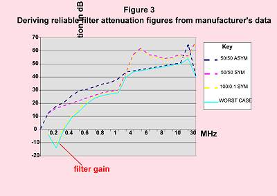
To deal with the impedance problem it is best to only purchase filters for which the manufacturers specify both common-mode (asymmetrical) and differential-mode (symmetrical) performance, for "matched" 50/50 Ohms and "mismatched" connections. Mismatched figures are taken with 0.1 Ohms source and 100 Ohms load, and vice versa. The trick is to draw an attenuation versus frequency curve consisting of the worst-case figures from all each of these various curves, and to take this as the filter's specification. See Figure 3 for an example of this procedure. When filters are chosen in this way to suit the predicted needs of the product their performance is usually as good or better than expected.

Most mains filters use common-mode chokes and rely on X capacitors connected between phases to deal with differential-mode interference. Filters which have to cope with high levels of low-frequencies from switch-mode convertors, phase angle power controllers, motor drives, and the like, often need more differential-mode attenuation than can be achieved by X capacitors, and may need to use differential-mode chokes as shown in Figure 4. It is difficult to get lots of differential-mode inductance into a small package because of core saturation, so these filters tend to be larger and more expensive.
Most mains filters use Y capacitors connected between phases and earth, with values of around a few nF so as not to exceed the earth leakage limits imposed by the relevant safety standard. The general rule that the Y capacitors should be connected to the conductor with the most noise on it (e.g. the mains cord in the case of a sensitive analogue instrumentation circuit, the rectifier of a switch-mode converter).
For medical apparatus, especially if patient-connected, the earth-leakage currents may be limited to such low levels that the use of any reasonable size of Y capacitors is impossible. Such filters need to use better inductors and/or more stages, and tend to be larger and more expensive. (Better still is to make the patient-connected end primary-battery-powered, communicating with the mains-powered equipment only through an opto-coupler or fibre optic link.)
In large systems the earth leakages from large numbers of small Y capacitors can create large earth currents. These can cause earth voltage differences which impose hum and high levels of transients on cables between different equipments. Modern best-practices call for equipotential three-dimensional earth bonding, but many older installations cannot achieve this so apparatus intended for use in larger systems often benefit from the use of filters with small or even non-existent Y capacitors.
It is always best to use mains filters for which safety approval certificates have been obtained from their manufacturer and checked for authenticity, temperature range, voltage and current ratings, and the application of the correct safety standard.
Ground noise is often overlooked in the specification of signal filters. Driver chips create ground-bounce noise, and if the RF bonding between the digital printed-circuit board's ground plane and the chassis is not perfect this can put a lot of digital 0V noise on all conductors too, so driver chips with specified low slew rates can still output high levels of RF noise.
Filters for low-frequency analogue signals, especially where the electronics is very sensitive, often need to be single or multi-stage circuits just like mains filters. In most cases, though, signals are digital or high-level analogue and not that sensitive, so simple R, L, C, RC, LC, tee, or pi filters are used, as shown in Figure 5.
R and L filters work by creating a high impedance to reflect the interference, but can usually only achieve a few dB attenuation. They are best used where the source and load impedances are low. L filters suffer from resonances and so are best made from soft ferrites (see below). R filters eventually lose their performance at high frequencies due to their parasitic shunt capacitance of around 0.2pF.
C filters rely on creating a low impedance to reflect the interference, and are best used where the source and load impedances are high. Performance figures for C filters usually look very good, much better than they achieve in real life.
RC filters with high R values are the most predictable because they cannot resonate in any very dramatic fashion, but the high R values (around 10k Ohms is often a good choice) may not be able to be used where there are signals of more than a few kHz or kB/s.
LC, tee, and p filters can provide higher levels of attenuation but suffer from resonances when connected to non-50 Ohms source and load impedances. This problem can be reduced considerably by the use of soft ferrites in the inductors. Soft ferrites act as inductors at low frequencies (sometimes up to 10MHz or so), but at higher frequencies they lose their inductance and act resistive. Ferrite beads with effective resistances of over 1k Ohms at 100MHz, but DC resistances of under 0.5 Ohms exist, providing the benefits of high resistance at frequencies which are not wanted, and low impedance at wanted frequencies. A huge range of SMD ferrite beads are available to suit a wide variety of signal spectra.
One of the secrets of RF filters is that they can never be very much better than the RF reference earth they are connected to. The only earths which qualify as RF references are solid ground planes in PCBs, metal plates, or metal boxes ("Faraday cages"), and ideally each of these should have no perforations greater than one-hundredth of a wavelength at the highest frequency to be filtered (3mm for 1GHz in air, or 1.5mm in FR4 fibreglass).
The connection between the capacitors in the filters and the RF earth should also be less than one-hundredth of a wavelength, and should have very low inductance. This means that green/yellow wires cannot be used as filter earths except for very low frequencies. For example, if a mains filter with Y capacitors of 2.2nF is earthed solely by a 100mm green/yellow wire its Y capacitors will be rendered ineffective at frequencies above 20MHz by the inductance of its earth wire.
Assume 1nH per millimetre for wire when working out the consequences of green/yellow earth connections. The only correct bonding for filters is direct metal-metal connection from filter body to the RF earth reference plane or box. It is of course acceptable to fit a green/yellow wire for safety reasons alone, as long as there is a direct RF earth bond.
Where a filter is mounted to a PCB its capacitors must bond directly to the ground plane. If there is no ground plane it is usually a waste of time fitting filters which use capacitors. Where a filter is fitted to a metal plate or shielding enclosure, it must bond metal-metal at all of its mounting points, and it may even be necessary to fit a conductive gasket under the filter body to make a seamless RF bond between its body and the metalwork.
Military signal filters tend to rely on C and p types because most traditional military equipment has a substantial and well-engineered RF earth (die-cast alochromed boxes bolted firmly to metal bulkheads in all-metal bodied machines and vehicles). This means that their earthed capacitors do not suffer from limitations caused by poor RF integrity of the earth.
Unfortunately, RF earth integrity is often a serious problem for household, commercial, and industrial products, since they have to be constructed with cost in mind. For this reason I have found that the most predictable signal filters in such applications tend to be RC, LC, or tee types, with the R or L element connected to the external conductor. This imposes lower levels of RF currents on the RF reference earth structure than would be the case with C or p filters.

Where a cable has a number of conductors in it, it often seems best to use a single common-mode choke for all the conductors, or maybe a single common-mode choke for each of the signals in the conductor if it is important to reduce crosstalk between sensitive signals. Figure 5 shows an example of a five-circuit CM choke used for a five conductor cable. SMD CM chokes are available with up to 8 circuits in a case size approximately 5mm cube.
The synergy of filters and shielding If a mains filter (for e.g.) allows 900MHz harmonics from digital processing to leak into the mains lead, the radiation of these almost-microwave frequencies from the mains lead will compromise the product's radiated emissions.
Another secret of RF filtering is that the correct way to view filtering and shielding is as a synergy, with each one complementing the other. Incorrect filter construction or mounting technique can easily compromise radiated emissions.
Where an external cable to be filtered enters a PCB with a ground plane or an industrial panel backplate used as an RF earth, the filters should be fitted to the PCB or backplate at the point of cable entry and directly bonded to their RF earth.
Where an external cable to be filtered enters a shielded cabinet, the filter should be fixed into the cabinet wall and bonded to the metalwork all around the aperture it fits in. Bulkhead filters are the best (e.g. feedthrough capacitors) but are often expensive to purchase and install.
Some types of signal connectors are available with built-in bulkhead filters, such as D-types (usually just 1nF capacitors, but ferrite, tee, and p types are also available).
For mains filters (which may usually be used from DC to around 400Hz with the same performance) the IEC inlet is the common commercial style of bulkhead filter. An IEC inlet filter with a metal body installed in a shielded enclosure can only give a good account of itself at frequencies above a few tens of MHz if its body has a seamless construction and it is electrically bonded all around its edge to the shielding metalwork as shown in Figure 6. Some manufacturers only aim their filters to work over the frequency range of the conducted emissions tests (up to 30MHz), making low-cost products that compromise the shielding integrity of their enclosure and cause the product to fail radiated EMC tests.
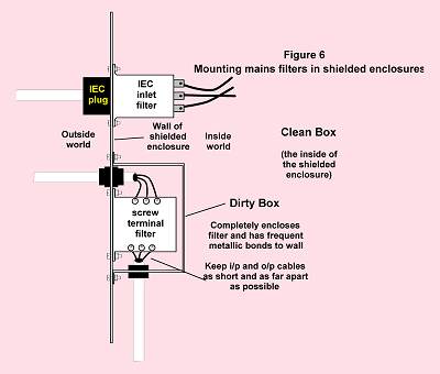
For high powers most commercially available mains filters use screw-terminal block connections, making bulkhead mounting impossible. Figure 6 shows a screw-terminal filter mounted using the "dirty-box" method, which encloses it in a shielded "dirty box" within the main shielded box. Even though the input and output cables in the dirty box are kept very short and far away from each other, high frequencies may still leak and ferrite cylinders may be needed on either or both cables.
Keith Armstrong is a Partner of Cherry Clough Consultants.
Phone: 01457 871 605, fax: 01457 820 145
e-mail karmstrong@iee.org
 © Nutwood UK Ltd 2001 |
Eddystone Court - De Lank Lane St Breward - BODMIN - PL30 4NQ Tel: +44 (0)1208 851530 - Fax: +44 (0)1208 850871 nutwooduk@nutwood.eu.com |
|
|
|